Triangulum problem

dlazzarini

Well-known member
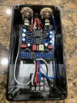
I’ve just recently built the Triangulum build. It’s a working build but something sounds off. When I turn the level up to a decent level or about half way up I get a really bassy heavily saturated sound that starts to cut out and break apart when heavy power chords are hit. Like it’s being overwhelmed. Ive got 9volts on pins 1/8 which are connected at VCC from what I can tell I’ve only got 5.6 volts 8DBB9F28-599C-4993-A220-943F1C6A6A8D.jpeg
 
Last edited:
Where are you measuring 5.6V? Do your electrolytic caps have the correct voltage rating? I can't read the IC part numbers in the pic. The best troubleshooting tool I can offer is a careful visual inspection. Most problems can be traced to a bad solder joint or a solder bridge. Those cheap stamped-pin IC sockets are also suspect. If you're gonna use IC sockets, I recommend spending a few extra pennies to get the machined-pin sockets. What is connected to the output of this pedal? The Level control is at the end, so it should have no effect on the circuit operation unless the next pedal in the chain is loading this one down.
 
Where are you measuring 5.6V? Do your electrolytic caps have the correct voltage rating? I can't read the IC part numbers in the pic. The best troubleshooting tool I can offer is a careful visual inspection. Most problems can be traced to a bad solder joint or a solder bridge. Those cheap stamped-pin IC sockets are also suspect. If you're gonna use IC sockets, I recommend spending a few extra pennies to get the machined-pin sockets. What is connected to the output of this pedal? The Level control is at the end, so it should have no effect on the circuit operation unless the next pedal in the chain is loading this one down.
Thanks for the advice. I’ve got the 5.6 volts at the VCC on schematic. All of the caps are more than adequate 35 to 50volts. I cannot find any bridged solder and I reflowed anything that looked suspect. I haven’t got to the point of putting the pedal in my board. As soon as you play on the heavy side is when it cuts out and crumbles. I’m new to building so I’ve still got a lot to learn. I’ll continue troubleshooting and hopefully find it. Thanks again for the advice. In the future I will use better sockets.
 
Let me make sure I'm following you. You are measuring +5.6V from pin 8 to pin 1 on IC1? What do you get when you measure from pin 1 to pin 3 on IC100? Are either of the ICs getting warm? Tell me what's going on with the red, white & black wires soldered to the Level control pads. What is supporting the board?
I like your granite countertop, I have the same pattern in my kitchen.
Sorry. Pins 1 and 8 I’m getting 9volts. I haven’t measured from 1 to 3 I don’t believe. Im not really sure yet where I’m supposed to measure to get the doubled voltage. I’m still learning. I was measuring somewhere around where D106 and C107 connect I believe when I got the 5.6 volts. The wires connected to the level pads are just soldered to the pot. I didn’t have the correct value pot with a PCB mount so I used one with lugs. I don’t yet have the board mounted on the standoffs. The pot housing is covered with a shell so I know it’s not shorting out. Do you know where I’m supposed to be getting the doubled voltage? I haven’t quite sorted that out.
 
[erroneous statement deleted by author]
Try this. Connect the - probe (the black one) on your meter to the ground lug on the output jack. Now touch the + (red) probe to IC100 pin 1. Record the reading. Now move the red probe to IC 1 pin 7. Record the reading.
The first reading should be close to +9V. The second reading should be close to +30V. IC100 is sometimes called a voltage doubler, but it's more than that. It's a voltage multiplier. Quick way to get an estimated output voltage for this configuration is to count the number of capacitors connected to IC100 pin 2 and add 1. Multiply that value by 9 (the voltage at IC100 pin 1). Now subtract 1V for each diode (D101 - D106). 9 * (3 + 1) - 6 = 30. This is a rough estimate; the diode drops might be a little less than 1V each depending on the load current and diode part #.
 
Last edited:
Now that I look closer at the schematic, the pinout for IC1 is wrong. Vcc goes to pin 7, not pin 8. Looks like it's correct on the PCB layout, so no worries.
Try this. Connect the - probe (the black one) on your meter to the ground lug on the output jack. Now touch the + (red) probe to IC100 pin 1. Record the reading. Now move the red probe to IC 1 pin 7. Record the reading.
The first reading should be close to +9V. The second reading should be close to +30V. IC100 is sometimes called a voltage doubler, but it's more than that. It's a voltage multiplier. Quick way to get an estimated output voltage for this configuration is to count the number of capacitors connected to IC100 pin 2 and add 1. Multiply that value by 9 (the voltage at IC100 pin 1). Now subtract 1V for each diode (D101 - D106). 9 * (3 + 1) - 6 = 30. This is a rough estimate; the diode drops might be a little less than 1V each depending on the load current and diode part #.
Thanks a ton for taking the time with me to help troubleshoot. I am not able to perform this at the moment but will let you know the outcome ASAP. Thanks again
 
Thanks a ton for taking the time with me to help troubleshoot. I am not able to perform this at the moment but will let you know the outcome ASAP. Thanks again
Ok I just used my meter as you directed. I got the 9volts at pin 1 on IC100 but the 5.6volts I was getting before is exactly what I’m getting at pin 7 on IC 1. I don’t think it’s the IC’s. I swapped them both out with 2 known good ones and have the same problem. I think I’ve got something else going on.
 
Unless it is a super bad quality 3pdt it should be fine I run my iron around 375 and it takes a brief hit to heat it up and then I fill it in. It might not/ probably is not the issue but it would eliminate a potential problem.
 
In any case, a bad stompswitch connection would not explain the low voltage at Vcc. Something in the charge pump chain is broken. Let's assume that each 1N4001 drops 0.6V. If the charge pump is completely dead, all of the diodes would be on all of the time and the voltage at Vcc would be
9 - (6 * 0.6) = 5.4V. Which is pretty damned close to the 5.6V you are measuring. If IC100 is known to be good, then there has got to be a bad connection somewhere. Inspect all of the solder joints on IC100 and C102 - C106. I think the IC socket is the most likely suspect. Once the tabs in those stamped metal sockets get sprung, they are useless. You're sure you're using a TC1044 for IC100, yes? I can't read the part number in the picture.
 
Unless it is a super bad quality 3pdt it should be fine I run my iron around 375 and it takes a brief hit to heat it up and then I fill it in. It might not/ probably is not the issue but it would eliminate a potential problem.
The glass transition temp of any epoxy they would use on those switches is well below 375F. I worry about messing up those switches after having a bad experience with a 4PDT switch. Those are big holes for rectangular solder terminals and it is not necessary to fill them up. Tack 'em on both sides and you're good to go. There is no mechanical stress on the solder joints. Rectangular holes would be much better. And more expensive.
 
In any case, a bad stompswitch connection would not explain the low voltage at Vcc. Something in the charge pump chain is broken. Let's assume that each 1N4001 drops 0.6V. If the charge pump is completely dead, all of the diodes would be on all of the time and the voltage at Vcc would be
9 - (6 * 0.6) = 5.4V. Which is pretty damned close to the 5.6V you are measuring. If IC100 is known to be good, then there has got to be a bad connection somewhere. Inspect all of the solder joints on IC100 and C102 - C106. I think the IC socket is the most likely suspect. Once the tabs in those stamped metal sockets get sprung, they are useless. You're sure you're using a TC1044 for IC100, yes? I can't read the part number in the picture.
Yessir it’s the correct IC. When I get a chance I will take your advice. Maybe get rid of the socket completely and solder straight to the board. I’ll let you know what I find. Thank you again.
 
The glass transition temp of any epoxy they would use on those switches is well below 375F. I worry about messing up those switches after having a bad experience with a 4PDT switch. Those are big holes for rectangular solder terminals and it is not necessary to fill them up. Tack 'em on both sides and you're good to go. There is no mechanical stress on the solder joints. Rectangular holes would be much better. And more expensive.
Everyone has their way I guess, but I still stand by my statement that the soldering on the 3pdt look sketch.
 
I would not solder the charge pump directly into your board, but would replace the socket if your socket is bad. Much easier to swap out a part if it is socketed so long as your socket is not the problem : ^ ) You can use your DMM to see if you have continuity between the pins on your charge pump and whatever they are supposed to connect to as shown in your circuit diagram.
 
Back
Top