You are using an out of date browser. It may not display this or other websites correctly.
You should upgrade or use an alternative browser.
You should upgrade or use an alternative browser.
A simple Relay Bypass
- Thread starter Chuck D. Bones
- Start date

what does the cost per board look like for this version? also, what kind of i/o jacks are you using for the other board?
szukalski
Well-known member
With an order of 5:what does the cost per board look like for this version? also, what kind of i/o jacks are you using for the other board?
- ~€3 per board without relay (this is mainly because there is a $7 setup fee for assembly, so the price should drop to ~€1.50 or lower once you go above 5)
- €1 for the relay
- €1.80 for the footswitch
- DC are DC-005
- 6.35mm are PJ-651A-01
Thanks.With an order of 5:
The IO jacks are from Daier:
- ~€3 per board without relay (this is mainly because there is a $7 setup fee for assembly, so the price should drop to ~€1.50 or lower once you go above 5)
- €1 for the relay
- €1.80 for the footswitch
- DC are DC-005
- 6.35mm are PJ-651A-01
szukalski
Well-known member
Because DIY is about sharing what you learn, what you get from others, paying it forward, and just having some sheepy love!

 github.com
GitHub - szukalski/pedal-simple-relay
Contribute to szukalski/pedal-simple-relay development by creating an account on GitHub.
github.com
steviejr92
Authorized Vendor
Ohhhhh I want me one of these! Thank you so much for the files!!!!Because DIY is about sharing what you learn, what you get from others, paying it forward, and just having some sheepy love!
GitHub - szukalski/pedal-simple-relay
Contribute to szukalski/pedal-simple-relay development by creating an account on GitHub.
damianvila
Well-known member
Ha
Though I need to move a few components from the bottom to the top to have everything in one side, since JLCPCB only assembles single sides.
If you already posted something about this that I didn’t see, I would appreciate you pointing me to it. Thanks!
Ha, ha! I also use JLCPCB and I’m thinking on buying parts directly from Daier to lower costs. Do you use EasyEDA? I would love a few tips about choosing specific components to generate an assembly order later.With an order of 5:
The IO jacks are from Daier:
- ~€3 per board without relay (this is mainly because there is a $7 setup fee for assembly, so the price should drop to ~€1.50 or lower once you go above 5)
- €1 for the relay
- €1.80 for the footswitch
- DC are DC-005
- 6.35mm are PJ-651A-01
Though I need to move a few components from the bottom to the top to have everything in one side, since JLCPCB only assembles single sides.
If you already posted something about this that I didn’t see, I would appreciate you pointing me to it. Thanks!
Smrtokvitek
Well-known member
Thanks a lot. Makes me wonder, what was the reason to use 0402 size components? There is a room for 0603 and maybe even 0805 and that would be a bit easier to hand solder.Because DIY is about sharing what you learn, what you get from others, paying it forward, and just having some sheepy love!
GitHub - szukalski/pedal-simple-relay
Contribute to szukalski/pedal-simple-relay development by creating an account on GitHub.
szukalski
Well-known member
Daier is great for hardware (switches, enclosures, knobs, jacks), LCSC is great for components in production (it's what JLCPCB uses), and JLCPCB is great for PCBs!Ha
Ha, ha! I also use JLCPCB and I’m thinking on buying parts directly from Daier to lower costs. Do you use EasyEDA? I would love a few tips about choosing specific components to generate an assembly order later.
Though I need to move a few components from the bottom to the top to have everything in one side, since JLCPCB only assembles single sides.
If you already posted something about this that I didn’t see, I would appreciate you pointing me to it. Thanks!
I haven't posted anything about the process, it took some multi-tasking to get the github repo set up
")
- I use DipTrace, but the same approach is true no matter what. You need to first get your component library setup, you can try and use an existing one but it's better to copy components from there into your own one for consistency (else you need to choose from 27 different 100k resistors each time).
- JLCPCB has a basic parts library which is best to stick to (any part outside that is extended and will incur a $3 setup fee per component type, they have to load the pick and place machine). I have shared my DipTrace library via the link in my signature, but EasyEDA has the JLCPCB basic parts library in any case..
szukalski
Well-known member
The pick and place robot doesn't complain about it. I just try and standardise my DipTrace component library. There are going to be instances where I need to go larger for power dissipation or because you can't get the voltage rating in that size, but 0402 is cheaper and smaller. What's not to love?Thanks a lot. Makes me wonder, what was the reason to use 0402 size components? There is a room for 0603 and maybe even 0805 and that would be a bit easier to hand solder.
The smaller size also does come in handy, this was my second SMT layout and I was trying to avoid excessive vias. I just did another boost which is roughly 1.2x1cm which will be really useful as an add-on for any build which wants a boost option.
damianvila
Well-known member
Thanks a lot! I haven’t thought of simply creating a library myself. I always suffer selecting from 200 similar components with different prices from EasyEDA’s interface…Daier is great for hardware (switches, enclosures, knobs, jacks), LCSC is great for components in production (it's what JLCPCB uses), and JLCPCB is great for PCBs!
I haven't posted anything about the process, it took some multi-tasking to get the github repo set up
- I use DipTrace, but the same approach is true no matter what. You need to first get your component library setup, you can try and use an existing one but it's better to copy components from there into your own one for consistency (else you need to choose from 27 different 100k resistors each time).
- JLCPCB has a basic parts library which is best to stick to (any part outside that is extended and will incur a $3 setup fee per component type, they have to load the pick and place machine). I have shared my DipTrace library via the link in my signature, but EasyEDA has the JLCPCB basic parts library in any case..
Thanks again.

cooder
Well-known member
Here's my implementation of the relay circuit.
Big cheers to Sir @Chuck D. Bones and the holy moly Boneyard!

Test fit:

Big cheers to Sir @Chuck D. Bones and the holy moly Boneyard!

Test fit:

owlexifry
Well-known member
The goal is to minimize cuts, jumpers and area. Pins 5 & 6 on the relay are n/c, so you don't need cuts at G11 & G15. It's fair game to make caps as long as you need to reach the desired strips.
Here's a scoring gauge I just made up:
1 point for each cut.
1 point for each jumper.
1 point for each unused hole. A hole is considered used if it is cut, covered by a component or jumper or used for an external connection.
It's like golf: lower score is better, it can be very Zen and it goes well with alcohol (not too much though).
My score:
12+8+10 = 30
That includes the jumpers on the solder side that join adjacent strips.
so currently tayda only has this option for 10-pin:
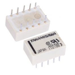
Mini Relay DPDT A-4.5W-K 4.5VDC 10PIN 2Poles 1A
FUJITSU COMPONENTS - Get It Fast - Same Day Shipping
 www.taydaelectronics.com
assuming 4.5V coil would be fine for 9V, but probably not for 12V or more.
so to allow use of a larger 8-pin DPDT, i did this layout:

(intended for this style relay)
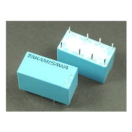
Mini Relay DPDT RY-9W-K 9VDC 8PIN 2Poles 1A
FUJITSU COMPONENTS - Get It Fast - Same Day Shipping
www.taydaelectronics.com

so how many demerit points do i lose for crossing jumpers? i know, it’s very naughty and brings shame on the family but i’m doing my best to keep it small

any errors?
(i haven’t yet recalculated the correct/actual value to replace the 150R, but i will)
Last edited:
szukalski
Well-known member
LCSC has suitable relays for cheap as chips and good shipping. If you're doing more than a couple relays, then having a vero may end up being a tedious, repetitive process for what is essentially a modular part. I just had 30 made with all the components on SMD except the relay for a buck a piece. With relay, it would have been ~$2.20 each (I just have an inventory of relays to use). That's not such a bad price if you build a lot of pedals.
Brett
Well-known member
If you’re using a 9v relay, you don’t need to drop voltage/current, so you’d just use a jumper.i haven’t yet recalculated the correct/actual value to replace the 150R, but i will
Chuck D. Bones
Circuit Wizard
YES.any errors?
That relay is not the size you think it is. Take another look at the datasheet.
See how I did that without quoting your entire post?
owlexifry
Well-known member
i’m probably only going to do like x3 max. i don’t do heaps of builds.LCSC has suitable relays for cheap as chips and good shipping. If you're doing more than a couple relays, then having a vero may end up being a tedious, repetitive process for what is essentially a modular part. I just had 30 made with all the components on SMD except the relay for a buck a piece. With relay, it would have been ~$2.20 each (I just have an inventory of relays to use). That's not such a bad price if you build a lot of pedals.
just wanted to whip up those few on vero.
thanks for the tipIf you’re using a 9v relay, you don’t need to drop voltage/current, so you’d just use a jumper.
That relay is not the size you think it is. Take another look at the datasheet.

is this not the same spacing as in my layout?
Chuck D. Bones
Circuit Wizard
Nevermind...
I was looking at the first Tayda link. Watch out for the height on the one you picked.
I was looking at the first Tayda link. Watch out for the height on the one you picked.
owlexifry
Well-known member
so when i first fired up the circuit it was immediately apparent that my layout (above) had the bypass/active routing backwards (LED on in bypass).
revised layout (for 12V circuit, 520R/9V coil):

verified

fitted it to a CE-2 build running @ 12V. was quite a squeeze.
but it works!
it's an awesome switch. i love it.
thanks for sharing this circuit @Chuck D. Bones
revised layout (for 12V circuit, 520R/9V coil):

verified

fitted it to a CE-2 build running @ 12V. was quite a squeeze.
but it works!
it's an awesome switch. i love it.
thanks for sharing this circuit @Chuck D. Bones
Chuck D. Bones
Circuit Wizard
You are very welcome.