SOLVED ADHD doesn't sound like an OCD (weaker gain less body/fatness)

ChrsGuit

Active member
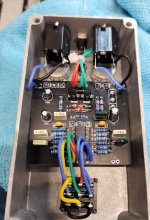
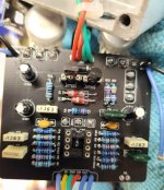
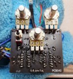
Just finished an ADHD build for a friend. This is the newest version of the PCB. My buddy loaned me his v 1.7 OCD to compare once finished... The Pedal sounds great, but is extremely lacking in volume, fatness, and gain... I went back and checked the transistors and silly stuff. All solder joints have been reflowed. Swapped the IC, etc. Don't get me wrong, pedal sounds great but it is very weak in the volume and gain department and I feel it sounds lacking to the genuine article... Something has to either be wrong on my end or I need to change some values to try and get it up to snuff. Any ideas what I should be checking first?
 

Attachments

  • Screenshot_20230820_222625_Instagram.jpg
    Screenshot_20230820_222625_Instagram.jpg
    850.6 KB · Views: 43
Check all your values definitely
That's my plan. I have to build at night after work and the family goes to bed, so I'll have to look it over later. The build docs aren't available yet but so far I've seen two schematics shared, both different. I built it using the values listed on the pcb, but apparently this pcb is capable of producing all versions so my theory is that perhaps I populated a component that was supposed to be omitted or a different value for the version I'm building... which would make sense... I've seen it before while building the "Super Stevie" high gain version... a resistor is supposed to be omitted and a pot value changed and if you populated it sans build docs you wouldn't know that
 
Looking at the board image on the website, it looks like the three Electro caps should be all be 10u. The one you have in C7 is larger than the other two - is that right?
 
Looking at the board image on the website, it looks like the three Electro caps should be all be 10u. The one you have in C7 is larger than the other two - is that right?
It is... I THINK I had to use a 50v because I was low on 25v's (have more coming). I'll double check it when I get home... Voltage rating shouldn't matter shouldn't it, so long as it's not under spec?
 
IMG_20230430_150619214.jpg


If you took out the germanium diodes, I can assure you the pedal will be screaming loud. I put those on a switch to add/remove the germanium diodes. Did the same thing the mosfets and a jumper. My pedal sounds plenty fat and gets very loud, so I'm guessing some component is not correct.
 
View attachment 54943


If you took out the germanium diodes, I can assure you the pedal will be screaming loud. I put those on a switch to add/remove the germanium diodes. Did the same thing the mosfets and a jumper. My pedal sounds plenty fat and gets very loud, so I'm guessing some component I'm not crazy about Germanium diodes anyway... silicon has always been just fine by me and they dont seem to have that weird rasp to them. I wonder if THAT is my issue. I used 1n34a's as the pcb called for... Curious if I can just swap them with a silicone equivalent
 
View attachment 54943


If you took out the germanium diodes, I can assure you the pedal will be screaming loud. I put those on a switch to add/remove the germanium diodes. Did the same thing the mosfets and a jumper. My pedal sounds plenty fat and gets very loud, so I'm guessing some component is not correct.
If you remove the germanium diodes from the circuit entirely, there will be no clippers to ground whatsoever as they are in series with the mosfets. If you jumper the germaniums, the mosfets alone will be quieter than mosfet + germanium in series.
 
View attachment 54943


If you took out the germanium diodes, I can assure you the pedal will be screaming loud. I put those on a switch to add/remove the germanium diodes. Did the same thing the mosfets and a jumper. My pedal sounds plenty fat and gets very loud, so I'm guessing some component is not correct.
I've been fiddling with it. To me it sounds ok if you crank the drive full blast, but it's almost like a bit of the clean signal is passing through... almost like a klon or bluesbreaker...
I pulled each mosfet individually while playing and the gain doesn't change noticeably... because it's like the gain is buried in the background
 
It sounds like your clipping doesn't work or you have a short somewhere. Check the solder side, maybe provide pictures, reflow and questionable joints.
I've reflowed multiple times, checked for any bridges or shorts. I spot-checked a few resistors to make sure I didn't accidentally put the wrong value in, even swapped some caps and diodes to be sure that wasn't the problem. I'm going to go through part by part this evening.
 
It sounds like your clipping doesn't work or you have a short somewhere. Check the solder side, maybe provide pictures, reflow and questionable joints.
Here's a better gut shot I took last night before I got it out of the enclosure. (I removed the IC to prevent heat damage while reflowing)
 

Attachments

  • Screenshot_20230821_174226_Gallery.jpg
    Screenshot_20230821_174226_Gallery.jpg
    883 KB · Views: 18
Are you sure about the germanium diodes? Especially their orientation. Theoretically it shouldn't be quiet if they don't work but if they are damaged or the wrong way around it might have some weird effects.
I know some Russian diodes are opposite (anode stripe) but I checked them with a tester first (for that reason) The distortion is certainly there, but it's almost like it lies beneath the clean signal...
 
You still didn't show and pictures of the solder side. It seems like something is either shorting out somewhere or there's a wrong value. The latter is a bit tedious to check without build docs I know. For anything more specific you'd need to start audio probing and check where the signal goes quiet, which is also a hassle without annotated schematic though.
 
You still didn't show and pictures of the solder side. It seems like something is either shorting out somewhere or there's a wrong value. The latter is a bit tedious to check without build docs I know. For anything more specific you'd need to start audio probing and check where the signal goes quiet, which is also a hassle without annotated schematic though.
I thought I mentioned that previously (maybe I didn't) I've got it apart and will post some photos tonight. With my work schedule and family stuff I have to fiddle with pedals after my wife and little boy go to bed. I used covers on my pots and am pretty meticulous on soldering so I don't have any shorts. I did notice a very tinyscratch on the backside of the pcb where a bit of the copper is visible... not in a trace, but near the edge of one. I doubt that would be an issue as nothing else is in that area. I would think if I had a dead short there I'd get no signal at all.

I'll post some photos in a bit. I'm going to compare mine to Michael's recent build, just eyeballing the resistors to see if I accidentally installed an incorrect value... and if I have to, go one by one to verify... I made that mistake before with a 51k that was actually labeled a "511 k" on the Boteh drive. Pedal sounded different than the previous ones i built, I compared them and found the mistake...
My poor old eyes aren't what they used to be.
I'll check back in later. I'm getting almost 9v at both sides of the diodes, which are fairly early in the circuit but 4.5ish at all legs of the JFETS. I'm going to take a good look at R4, R5, etc and make sure those are proper values... I've already confirmed all caps are correct, so I'm wondering if I'm not applying enough/too much resistance early in the chain...
 
You still didn't show and pictures of the solder side. It seems like something is either shorting out somewhere or there's a wrong value. The latter is a bit tedious to check without build docs I know. For anything more specific you'd need to start audio probing and check where the signal goes quiet, which is also a hassle without annotated schematic though.
Forgive the slopy Flux mess. I had it cleaned up fairly well til I started reflowing joints I'm seeing no shorts or bridges
 

Attachments

  • Screenshot_20230822_170553_Gallery.jpg
    Screenshot_20230822_170553_Gallery.jpg
    841.1 KB · Views: 18
You still didn't show and pictures of the solder side. It seems like something is either shorting out somewhere or there's a wrong value. The latter is a bit tedious to check without build docs I know. For anything more specific you'd need to start audio probing and check where the signal goes quiet, which is also a hassle without annotated schematic though.
I think I might be dealing with a dead gain pot... I tested and get 516k on the first leg (pot knob facing me, (ohms, to center) but nothing on the third leg to center...
 
I know some Russian diodes are opposite (anode stripe) but I checked them with a tester first (for that reason) The distortion is certainly there, but it's almost like it lies beneath the clean signal...
As long as they are opposite of each other, the silkscreen orientation doesn’t matter so much.
 
Back
Top