Solder of Destiny
Member
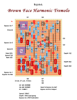
I'm trying to translate this stripboard layout diagram to a 3PDT wiring board and my head hurts. Can anybody tell me where on the stripboard to connect the switch board's in and out (BI and BO)?
Right, but where on the main board are the corresponding BI and BO connections?The lugs are numbered like this
1 4 7
2 5 8
3 6 9
Look on the stomp board to see where the solder pad traces are connected to those lugs.
I think that's jack in/out?Check the bottom right of the layout for IN/OUT directions
Bypass 5 on the main board is board in and bypass 7 on the main board is board out.Right, but where on the main board are the corresponding BI and BO connections?
Yes, I have more or less finished it with the small issue that it is not working. The LED is flashing and the speed pot affects it but no sound. I'm not really sure how to wire the footswitch so that might be the issue.Have you already started building this project?
Annoying. I'm sure you've maxed out the level trim pot?I just wanted to warn you that the one I had had a volume drop.
Yes that’ll fix it but for some reason i didn’t care for the pre or something. Now that I’m thinking about it though I remember mine was version 1 they went back and fixed some things and made it better. Probably best to disregard what I’ve said. Unless you’re building version 1.Annoying. I'm sure you've maxed out the level trim pot?
I can't get it working anyway. I think I might hate stripboard.Yes that’ll fix it but for some reason i didn’t care for the pre or something. Now that I’m thinking about it though I remember mine was version 1 they went back and fixed some things and made it better. Probably best to disregard what I’ve said. Unless you’re building version 1.
I can't get it working anyway. I think I might hate stripboard.
I guessed that the 3PDT board might be the problem so I rewired it directly to a fresh 3PDT two days ago.Did you look at the schematic for the BYOC Brown Face Tremolo? If so you'll see that it is not compatible with the bypass switch you are using--which is why the stripboard diagram tells you how to wire it directly to the switch rather than just specifying input and output like other circuits.
You should just wire to the switch directly as specified in the layout.
I think there is a way to make it work if you're creative--it would mean not using the LED or resistor and wiring one of the connections directly into one of the led's pads, but at that point, the board isn't adding much value so you might as well skip it.
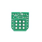
Yeah, my eyesight is definitely an issue soldering to stripboard. I ordered a magnifying visor, which unfortunately arrived when the board was mostly done. I will concede that the soldering is on the messy side. That said I'm getting continuity everywhere I should, and no continuity everywhere I shouldn't.Strip board is a lot easier to troubleshoot IMHO. No hidden traces. What I like to do is take a pic of the back side and zoom in on it. You can see bridges and bad solder joints easier.
...
I had a look at the schematic in the BYOC build document. It's practically illegible. ...


I did not. I made an eagle file from the schematic for a friend who sent me a pcb.Yeah, my eyesight is definitely an issue soldering to stripboard. I ordered a magnifying visor, which unfortunately arrived when the board was mostly done. I will concede that the soldering is on the messy side. That said I'm getting continuity everywhere I should, and no continuity everywhere I shouldn't.
The magnifier is great for well-lit close-ups. I'm pretty confident there are no bridges.
Did you build yours on stripboard? Any chance I could see a pic of your switch wiring to the board?