Deofol OD

Musikding might have an outdated PCB... I don't have the layouts in front of me on this PC so I can't say if Rev 2 is the absolute newest revision.

Let me look into this and try to make sense out of it.

There has been a lot of debate on multiple forums about the orientation of that capacitor and it seems that oscillation has been an issue on other PCBs and vero layouts as well..... I might have no choice but to just buy one and trace it myself.
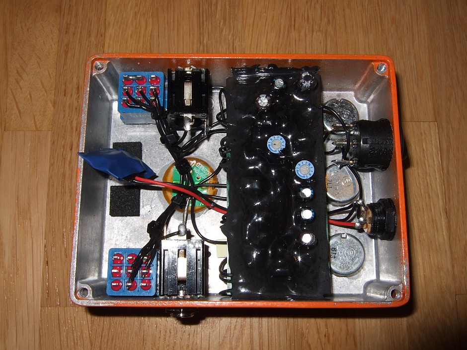
There have been some Duds drawn up of this circuit.
When it was first available, it had Epoxy all over it.
Later versions don't have Epoxy,
3218841850_b2b693565b_o.jpg

img-5981-1303220002.jpg
 
I can't find a single picture of an original unit with the Gain, Tone, and Level trim pots.....
 
OK so I think I've found the problem. There is an error in the schematic that raises gain circa 2 times in every gain stage.

This is revision 2


This is the schematic that can be found on the internet with the different connections of C4, C9 and Bass+ trimmer.


This is the quick simulation in LTSpice to see the effect


I will try to fix it on the PCB tomorrow probably.
I don't trust Internet schematics. Seen too many wrong ones.
It's true that moving the bootstrap caps above the source resistors lowers the gain. It also raises the output impedance and makes the circuit more sensitive to loading. Plenty of pedal circuits have the bootstrap caps from source to gate, but I have yet to see one that has a source resistor below the cap.

High-gain circuits are very sensitive to layout and grounding. Not just on the board; the off-board wiring and grounding has to be carefully laid out too.
 
I don't trust Internet schematics. Seen too many wrong ones.

Absolutely. If it's not a classic circuit with plenty of confidence backing it (Fuzz Face, Muff, TS, etc) then I'm going to have to trace it myself these days.

Not saying there weren't good intentions, or that I don't make mistakes myself, but I've been bitten too many times.

I'm working on getting one of these now so we can find out once and for all, then I'll rework the entire PCB layout to try and address any oscillation problems.
 
I am defintely keen to find out about the correct schematic of this! I have the Deofol as per earlier pcb built but I find that have to have the tone control always dimed otherwise it sounds flat and dull.
 
From those gut shots it looks like a lot fewer parts than the one I built, which I never bonded with and sent to a buddy
It looks like it but there are different versions of this type of Diablo. There is a Gain+(pedalpcb) that has a switchable gain stage with trim pot adjustments and there is something like Boost+ (the photo from music6000 probably) which has only a different pot (setting of gain) that is changed by the switch.

I've just tried to "beep" my PCB and it looks like it is routed according to a schematic from the rev2 document I have posted. So I could try to relocate the capacitors connections to see if it helps.
 
There is a Gain+(pedalpcb) that has a switchable gain stage with trim pot adjustments

See that's what I was thinking too, but this guy does a review of the Gain+ and only mentions two internal trim pots. (Bass and Presence)

I'm really concerned that we've fallen victim to another case of "This is probably what's in there" or "This would be better if it were like this"...

As far as I can tell there are zero photos of the unit that was traced for the schematic that has been passed around the net.
 
Great - waiting for the schematic here as well.
I kinda made it work for me, by keeping it on the verge of oscillation (removed the low pass filter that made it sound dull, did a few more trimmers for biasing the trannies) and with careful gain staging and operating it sounds good.
But this feeling that - "I am missing something" ... :)
 
I moved those 2 caps yesterday and it helped but it did not solve the oscillation problem totaly. The gain is definitely lower and the oscillation is still there but only at the very end of the gain pot. I will try to select transistors with higher Vp. Right now I have all of them in the range from 0.7V to 0.8V.
 
I checked my notes and I put a 100R trimmer in place of R9/R8 (at Q3 source) and played a bit with the bias - it also works in the right direction. Now, I am coming mostly from tube/valve technology - but the caps in discussion will be a typical bypass cap arrangement in one case (i.e. cap across the resistor) providing more gain and wider frequency response. While on the "Internet" schematic, it would be similar to providing for negative feedback and stability purposes, i.e. taming the high frequencies (albeit with tubes these are typically in the pF range and combine with the inherent Miller capacitance of the tube, etc, etc).
In short, this might make sense - nevertheless - an affirmation would be great.
And I might also pull the PCB out of the box and try that change :)
 
Last edited:
I still have to pull and measure all the caps, but here's what I can tell you so far...

The capacitor in question is directly across the Gate/Source. The original schematic was correct in that regard before folks did their "magic".

However... the Body control is completely different. Granted this version uses a toggle switch instead of a pot, and it's entirely possible that the functionality was changed at some point, but it's not the same.

There are also one or two component differences.
 
Back
Top