Did I fly to close to the sun (and fry my FV-1)?

p_wats

Well-known member
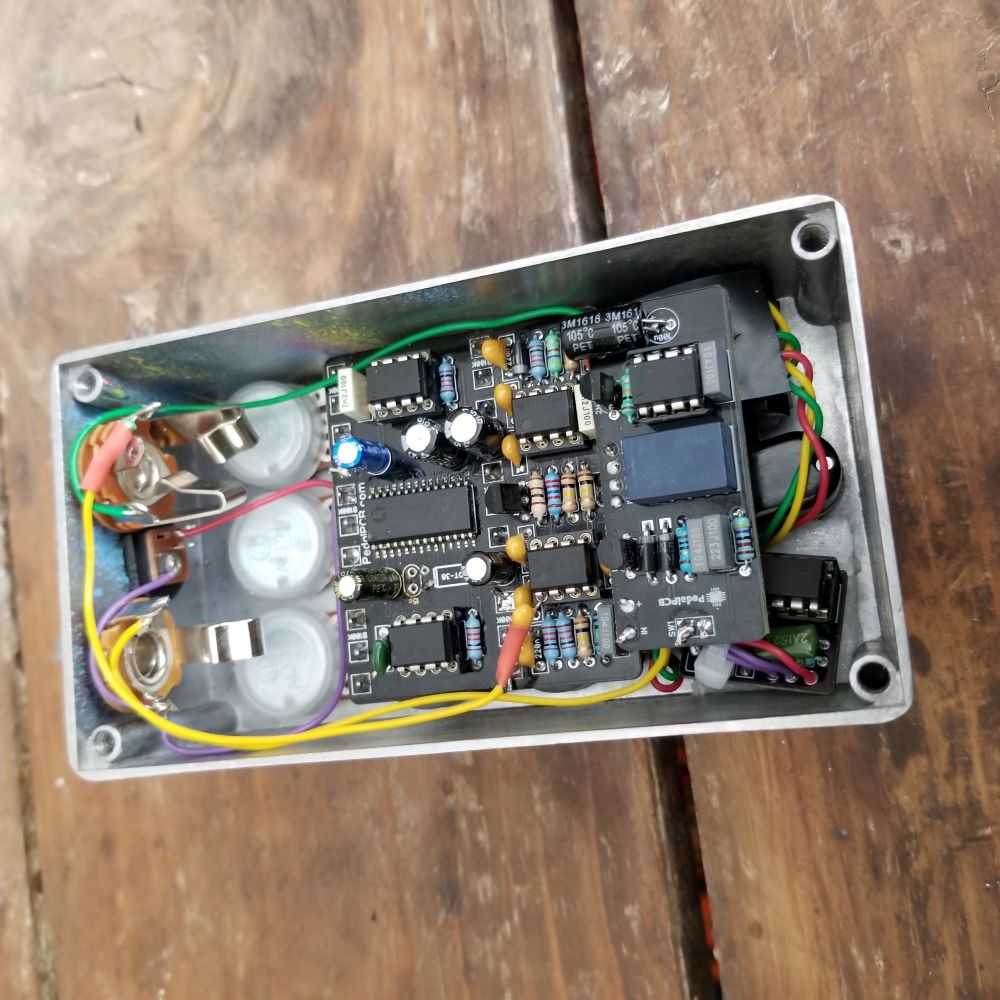
I posted this build of an old Arachnid board with some mods and everything was working perfectly, until I tried to push it a little further. I wanted to build a little daughter board to sit in the EEPROM socket and switch between 2 EEPROMS (as per this post), but needed to adapt the layout in that thread to fit the older board (EEPROM on the opposite side of the board).

Something appears to have gone wrong, as now the circuit in general doesn't work (I've removed the EEPROM daughter board).

I didn't find any shorts in my daughter board that would have sent 3.3v to the wrong spot, but I now get no output from the FV-1 (not even using the internal programs).

  • Using my audio probe I get sound at pins 1 & 2 of the FV-1, but nothing at pin 28.
  • I've got 3.3v to all the correct pins and also ground where required.
  • Mix and volume controls work as expected, reinforcing that maybe I somehow killed the FV-1 itself.

Anything else I should check for?

I've got a rework station, but I doubt it's going to be easy to get this FV-1 off the board and replace it without doing some damage.
 
You may be able to remove the bad chip using your rework station and not damage your PCB.

I think the best way to replace an FV-1 is to order some specialty low temp solder. You wick away as much of the regular solder as you can, add the new solder and it stays liquid long enough for you to heat both sides and remove the fv-1. you can find youtube videos for people using this to replace CPUs on motherboards.

here is an example from amazon. not cheap, but cheaper than your replacement FV-1 chip, and good to have in reserve:
https://www.amazon.com/ChipQuik-SMD...ild=1&keywords=chipquik&qid=1596838670&sr=8-1
 
I've got a rework station, but I doubt it's going to be easy to get this FV-1 off the board and replace it without doing some damage.

Removing the FV-1 isn't all that bad, if it comes to that.

If you have a pair of sharp diagonal snips you can just clip each pin at the body of the IC (carefully), toss the IC, then desolder each pin one at a time.

MFG_CHP-170.jpg


I should add though, I can't think of anything here that would have damaged the FV-1.... They're pretty dang tough, I've seen them survive reverse polarity AND overvoltage.

Good to know! Thanks.

If I'm getting signal on the way in (pins 1&2) but none on the way out (pin 28) and all power/ground looks fine, is there anything else to test other than replacing the FV-1?

I'm also worried about how I'll get a new one in there without making a mess of everything, given the other components are already on the board (ie, would it be better to just ditch this and upgrade to one of the newer boards anyway?).
 
Thanks for the suggestions so far!

I've done some more probing/measuring/reflowing joints, etc. and still no luck.

The closest thing I can think of is that my daughter board going into the EEPROM socket may have sent 3.3v to the wrong pin, but even that seems unlikely.

In any case, I need to put this away for a while for my own sanity. If anyone has any other troubleshooting ideas before I try to remove the FV-1 I would love to hear them!

I've got an even older Octagon board (all 1uf electrolytics instead of MLCCs, etc.) that I may just pop in this box instead with the other mods I had done, but it would be nice to salvage this board too if possible.
 
post some pics of the board if you want other suggestions of things you could check.

Good news/bad news:

It seems as though the initial problem may have been caused by the clock expression jack not connecting properly (it was working fine all week, but maybe something went wrong after using it the other night).

I now get the effect on the output. It even sounded fine for a bit, but now emits a high-pitch squeal with the wet signal.

I think what has happened is I've made matters worse grasping at straws, so cables have broken, etc.

I'm taking a sanity break for a bit, but at least there has been some progress. Now to figure out what could cause the squeal.

Here's a board pic from before I started going crazy with troubleshooting. It's looking worse now unfortunately.

arachnid-relay-clock-exp_02.jpg
Good luck. That looks epic.
 
Thanks!

More good news/bad news this morning:

- Internal FV-1 programs are working, but ONLY the internal ones. Pin 13 still seems to be getting 3v, so I'm perplexed (I've also tried the EEPROM in a working build and it is fine)

- The clock module seems to be working, but at the end of the pot range is now a loud, horrible noise (oddly, this is gone when I use the expression jack, but I attribute that to maybe a slightly different pot tolerance?). To be sure I've removed the clock module and gone back the crystal for now.
 
Last edited:
you likely have a problem in the connections between the eeprom and the fv-1. check out the path using the schematic and your dmm

Thanks. Yeah, that would make sense. Though all continuity and voltage seems fine in that area, so I'm a bit stumped.

I've now pretty much reversed any mods that had been done, re-checked everything and replaced a few components, just in case, but still only get the internal FV-1 programs (I've also swapped EEPROMs, just in case).

Pin 13 is not grounded and measures 3.3v.

For the EEPROM the pin details are the following:

1 - To ground (measures 0v)
2 - Ground (0v)
3 - Ground (0v)
4 - Ground (0v)
5 - To FV-1 pin 15 (3.3v)
6 - To FV-1 pin 14 (3.3v)
7 - Ground (0v)
8 - To 3.3v

Which matches the schematic as far as I can tell.
 
Thanks!

More good news/bad news this morning:

- Internal FV-1 programs are working, but ONLY the internal ones. Pin 13 still seems to be getting 3v, so I'm perplexed (I've also tried the EEPROM in a working build and it is fine)

- The clock module seems to be working, but at the end of the pot range is now a loud, horrible noise (oddly, this is gone when I use the expression jack, but I attribute that to maybe a slightly different pot tolerance?). To be sure I've removed the clock module and gone back the crystal for now.

Plot thickens! Been enjoying this thread. Fingers crossed it gets sorted!
 
Alas, still no luck.

Internal sounds only even though all connections and voltages around the EEPROM look good. I assume the problem would lie somewhere either at pin 13 of the FV-1, but that measures 3.3v, or at connection issues between pins 14 & 15 of the FV-1 and pin 5 & 6 of the EEPROM, but continuity looks good there too.

It seems like the FV-1 is working, at least, so it may be possible to transplant it to a new build, but has anyone (most likely @PedalPCB ) ever seen an FV-1 that seemed locked to the internal programs before?

Is there anything else I can check before throwing in the towel (the only "mod" still left is the relay bypass board, as that's attached by pin headers)?

I was thinking about trying to remove the EEPROM socket and try a new one, just in case there's something wonky there, but that will be a pain and continuity measures as it should.
 
I don't recall seeing behavior like that before.

I've seen one where turning the pots didn't change any parameters until you switched modes, but beyond that they usually either work correctly or don't work at all.
 
I don't recall seeing behavior like that before.

I've seen one where turning the pots didn't change any parameters until you switched modes, but beyond that they usually either work correctly or don't work at all.

Thanks. That at least gives me hope that maybe I can remove this one and put it on another board.

That said, if it's not the FV-1 or the EEPROM it has to be something simple on the board itself that I've probably inadvertently messed up while modding/troubleshooting that's now stopping it from using the EEPROM, but I can't think of anything else to check other than continuity and voltages (along with cold joints/bridges, etc.).

Any other ideas?
 
have you checked all the pins on the fv-1 to make sure nothing is grounding that should not be, and that nothing is getting voltage that should not be? I don't think you can tell at this point if the problem is on the chip or on the board. In addition to trying your eeprom in another pedal (which worked), have you tried putting another working eeprom in this pedal to see if it works?
 
have you checked all the pins on the fv-1 to make sure nothing is grounding that should not be, and that nothing is getting voltage that should not be? I don't think you can tell at this point if the problem is on the chip or on the board. In addition to trying your eeprom in another pedal (which worked), have you tried putting another working eeprom in this pedal to see if it works?

Thanks. I've tried a few different EEPROMs from other working pedals (as well as all other swappable chips).

I've done continuity checks on all pins of the FV-1 and followed the schematic (but will do so again, just to be sure).

In terms of voltages, I've compared with a working Arachnid and everything is nearly the same except for pin 27, which is 1.6v on this build and 2.0v on my other build, but that pin isn't connected in the schematic, so I assume that doesn't make much of a difference.
 
for the eeprom, have you compared the measurements to a working fv-1 pedal? I checked one of my fv-1 pedals and have no significant voltage on pins 5 and 6 when the pedal has 3.3 volts on pin 8 (less than 1 milivolt)
 
for the eeprom, have you compared the measurements to a working fv-1 pedal? I checked one of my fv-1 pedals and have no significant voltage on pins 5 and 6 when the pedal has 3.3 volts on pin 8 (less than 1 milivolt)

I have 2 other working Arachnid's and measured those: all 3 (including the one I'm troubleshooting) measure 3.3v on pins 5, 6 & 8 of the EEPROM, regardless of a chip being installed in the socket or not.
 
Back
Top