
Last edited:
You are using an out of date browser. It may not display this or other websites correctly.
You should upgrade or use an alternative browser.
You should upgrade or use an alternative browser.
Flock Harmonizing Fuzz - Arriving Soon!!!
- Thread starter music6000
- Start date
First In, First Served!Dang it! I knew I should of rage ordered at work when I had it in my cart. This one I almost considered buying the real one.
Robert
Reverse Engineer
Dang it! I knew I should of rage ordered at work when I had it in my cart. This one I almost considered buying the real one.
More are on the way, this was a small prototype batch.
1 pole 12 position switch? Alpha SR2511 work?More are on the way, this was a small prototype batch.
Robert
Reverse Engineer
1 pole 12 position switch? Alpha SR2511 work?
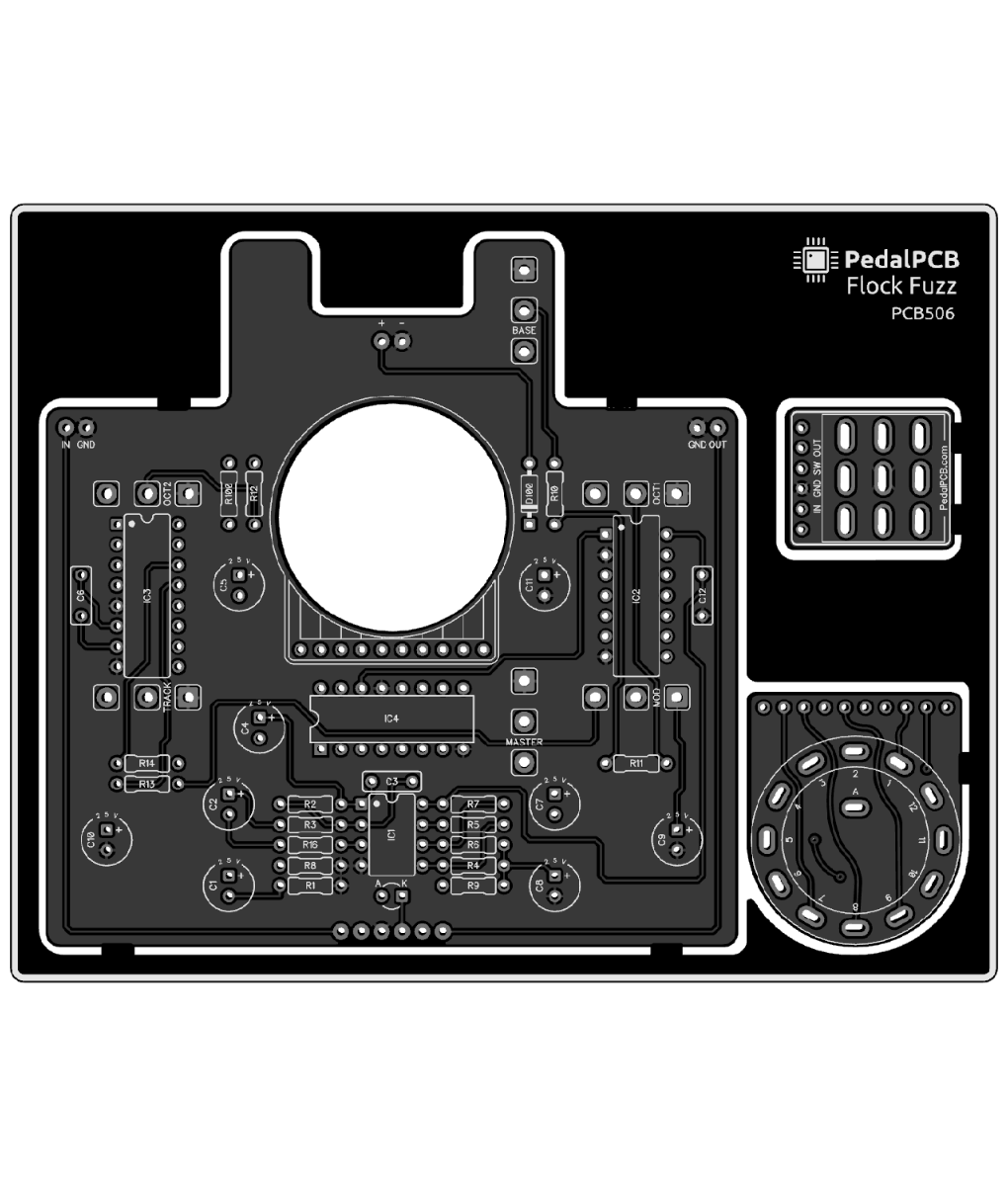
The PCB was designed for the SR2612F type rotary switches. (or SR2611F with the solder eyelets clipped off)
This one needs to be the 1 pole - 12 position adjustable type so you can restrict it to 9 poles.The PCB was designed for the SR2612F type rotary switches. (or SR2611F with the solder eyelets clipped off)
This is done with a adjustable locking washer at the base of the shaft to go from 2 positions to 12 positions.
It takes a 3/8'' or 10mm mounting hole!
Ctrl4Smilerz
Well-known member
Awesome, really looking forward to building this one. Does anyone know if this circuit is a PLL? I thought I had read that somewhere, but can't find it now.
Bricksnbeatles
Member known well
Indeed it isAwesome, really looking forward to building this one. Does anyone know if this circuit is a PLL? I thought I had read that somewhere, but can't find it now.
Yeah definitely am gonna wait and finish my 4th of July order before ordering one of these too xD. Kinda glad they sold out fastApparently not available right now. It was until I went to add to my cart. I was too slow. Maybe it was a sign I need to build what I already have.

Here's a good read! :Awesome, really looking forward to building this one. Does anyone know if this circuit is a PLL? I thought I had read that somewhere, but can't find it now.
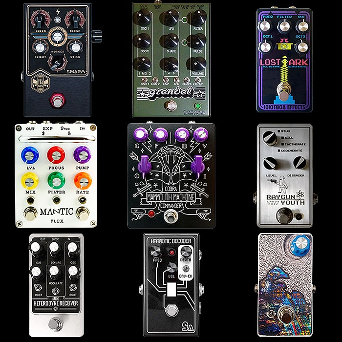
9 of the Best Compact and Medium Format Schumann PLL Style Harmonizer Fuzz Pedals
Guitar Pedals, Guitars and Amps - contextual overviews and comparisons, insights and recommendations
Based on a photo of the original circuit, is:Very excited for this! What are the ICs?
- TL022
- CD4017
- CD4024
- CD4046
Problaby is the same ICs for the Flock!
G.G.
Well-known member
Can anyone give their elevator pitch for the difference between the Swarm & the Data Corrupter? I watched a few vids and really liked the sounds in ThePedalZone Data Corrupter vid, but not so much in others. Maybe depends who's playing it? The Swarm sounds interesting too but again depending on who's playing it. Any thoughts?
DGWVI
Well-known member
I feel like they left out Parasit's best PLL- the Into the Unknown. I'm also quite fond of the MultiwaveHere's a good read! :
9 of the Best Compact and Medium Format Schumann PLL Style Harmonizer Fuzz Pedals
Guitar Pedals, Guitars and Amps - contextual overviews and comparisons, insights and recommendationswww.guitarpedalx.com
Robert
Reverse Engineer
I've decided to make an update to the Flock PCB....
I initially wanted to avoid a breakout board for the rotary switch because someone inevitably will install it upside down on the rotary, but after some debating with myself I've decided to go ahead and go that direction.
The rotary switch puts the PCB at a height where 16mm pot pins just barely make it. It's absolutely doable, but a little tricky to assemble.
Washers under each pot (inside the enclosure) can lift them up enough that this is not an issue at all, but in the end I decided it'd just be easier to include a breakout board.
I've also updated the rotary switch footprint to work with the solder lug rotary switches available from Tayda Electronics, since the PCB pin mount versions can be harder to find. No lead clipping required!
If you received one of the first revision PCBs and would like the updated board just shoot me a message.

Last edited by a moderator:
Dan0h
Well-known member
Saw this and thought they were in stock….I've decided to make an update to the Flock PCB....
I initially wanted to avoid a breakout board for the rotary switch because someone inevitably will install it upside down on the rotary, but after some debating with myself I've decided to go ahead and go that direction.
The rotary switch puts the PCB at a height where 16mm pot pins just barely make it. It's absolutely doable, but a little tricky to assemble.
Washers under each pot (inside the enclosure) can lift them up enough that this is not an issue at all, but in the end I decided it'd just be easier to include a breakout board.
If you received one of the first revision PCBs and would like the updated board just shoot me a message.
View attachment 30385
jeffwhitfield
Well-known member
Other than the updated rotary, if everything else is the same, I'll be happy to just stick with the first revision. No biggie.I've decided to make an update to the Flock PCB....
I initially wanted to avoid a breakout board for the rotary switch because someone inevitably will install it upside down on the rotary, but after some debating with myself I've decided to go ahead and go that direction.
The rotary switch puts the PCB at a height where 16mm pot pins just barely make it. It's absolutely doable, but a little tricky to assemble.
Washers under each pot (inside the enclosure) can lift them up enough that this is not an issue at all, but in the end I decided it'd just be easier to include a breakout board.
I've also updated the rotary switch footprint to work with the solder lug rotary switches available from Tayda Electronics, since the PCB pin mount versions can be harder to find. No lead clipping required!
If you received one of the first revision PCBs and would like the updated board just shoot me a message.
View attachment 30385
")
Good tip on the pots. I might end up using the longer lead pots for mine to avoid any issues with the height.
Similar threads
- Replies
- 10
- Views
- 1K