SOLVED How to reverse "flipped" PNP circuit back to positive ground?

MBFX

Well-known member
EDIT: THE SOLUTION IS TO UNDERSTAND THE DIFFERENCE BETWEEN POWER AND GROUND VS. POSITIVE AND NEGATIVE POLARITY. IF YOU THINK IN POLARITY, YOU'RE FUCKED AND YOUR PEDAL WON'T WORK.

The way to edit the veroboard layout below is to flip the electrolytic capacitors around. Remove the diode, because it's the wrong way in the vero layout as posted and it's better to have it on the barrel connector. Connect the power rail (labeled 9V) to the sleeve of your barrel connector. Connect the ground rail to the tip. From there, you're going to want to plug it in - make sure you are using a "backwards" power cable, such as this:

You can make one, but I've had a hard time finding DC connectors small enough to be worth it.


-----------------------------------------------------------------------------------------------------

Original post:


The following PNP Germanium transistor using circuit references negative voltage. I want it to reference positive voltage, so it can be in the same box as a positive reference voltage Germanium Fuzz Face, using a shared Lumberg power connector. No battery. I am too inexperienced to simply walk into Mordor.

I look at the schematic, and I can understand the difference. On a breadboard, I understand the difference. I look at this vero layout, and my brain short circuits. What is the actual difference here? I don't understand how I would change it to make the positive rail Vref.


VERO LAYOUT I USED, PRETEND THE DIODE ISN'T THERE:

1704900099724.png

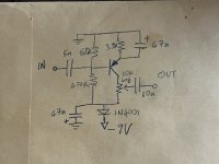
SCHEMATIC FOR ABOVE, PRETEND THE DIODE/OTHER WEIRD THINGS AREN'T THERE:
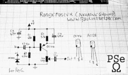
1704900127900.png
 
Last edited:
You’re going to need to flip the polarity of all the diodes and El caps. You’ll then need to make sure you do the same with the transistors. Reverse the collector and emitter positions.
 
I’m not sure I understand your question but it looks to me like both of these circuits require negative Vcc, that is the power rail is negative (because they use PNP transistors). If you’re using a battery, you can accomplish this by connecting the negative pin to Vcc and the positive to ground (that’s where the term “positive ground” comes from, but I find it more confusing). In the layout for the FF you have a -9V pin and a ground pin: you should be able to connect those directly to the negative and positive battery pins respectively. On the RM layout there are pins for 9V and ground, so you should be able to connect them to the positive and negative pin respectively (I think these are actually mislabeled and they should be ground and -9V respectively but that’s irrelevant).

Now if you’re using a power adapter you’re going to run into noise issues if you try the same trick. That’s because ground is a bit of a different concept on the power grid.

I hope that helps!
 
When I read that, it feels like I'm not taking something into account.... bear with me.

Forgetting the diode (I put them on the power connector), I reverse the order of the caps and transistor, and the power leads. Aren't the resistors now connected to the wrong legs of the transistor? Do I need to account for that, and redraw the vero layout "mirrored"? Same question re: the pot, since when I flip the transistor but nothing else it's now tied to emitter
I see what you’re saying about the transistor legs. While I don’t have a scientific answer for you…the transistor will still function correctly, the resistors will be in there correct spots regardless of the reversing of polarities. The truth is by “flipping” the circuit, the emitter now takes on the job of the collector and so it needs the collectors network in order to function and vice versa.
 
That schematic is drawn oddly. The 9v + is written twice, and is meant to be all ground wires. -9v is all power. If the diode isn't the right way or the caps +/- isnt seeing the same polarity it also won't work. Don't have any other pedals plugged into the power supply or daisy chain.
 
Ok sorry I clearly haven’t had enough caffeine today. I see what you’re saying. It should be easy to convert the RM to “positive ground”. I need pen and paper to work through that since I am having a hard time understanding the schematic you posted. In particular the +V pin connected to the diode seems fishy (could it be a mistake?) because the other side is then connected to ground.
 
I rewrote the schematic to use negative power (“positive ground”). It’s basically the same as the original with different rails and the diode mistake corrected. That 47nF cap for power filtering seems a bit low, maybe they meant 47uF? Also I don’t think that 47nF across the feedback resistor has to be polarized, you should be able to use a film cap or box cap.
Anyways here it is:

IMG_0714.jpeg
 
Functionally my schematic uses a different ground plane. That means all ground connections will go to this other plane rather than the one you had before. This includes jack sleeves. I assume this is reflected in the vero layout somehow? I’ve never used vero, although it should be pretty simple.

How are you powering the FF?
 
Because EE's cannot seem to agree on a convention for drawing positive ground vs. negative ground circuits, this always seems to come up. And this is (one reason) why we can't have nice things. I recently saw this same problem recur on another forum and it made me depair for humanity there as well. It's hard enough to follow the electrons when things are drawn up consistently!

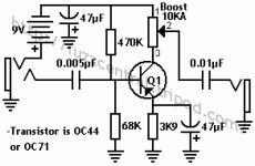
If you use this schematic as a guide:

rangemasterschematic.gif
instead of (presumably) the widely-spread ElectroSmash one (which is technically correct—the best kind of correct—except when you want the circuits to play nicely with each other together in the same box), you can more easily see which buss is now actually ground (the one with the non-tranny ends of the 68K and 3.9K resistors and the positive end of the Q1E 47µF 'lytic) and which one is connected to the –9V power line (the far end of the 470K, the negative end of the power filter 'lytic, and the anticlockwise side of the boost pot). So on your vero, what is labelled as "ground" should go to power; –9 volts power. And what is given as "9V" is actually genuinely ground. I can't see where those wires go in your pic (and all-black wire also kinda makes it harder to see), but assuming everything else is wired correctly, reversing just those two on the RM board ought to do it. (I hope!)

edit: you might also want to check those polarity protection diodes at this point – they may have done their jobs, but at the cost of their lives o_O...
 
Last edited:
I deleted the photo of the box because it isn't useful to get the answer I'm looking for.

I didn't use diodes on the board, but rather a single one on the power connector itself. Gives me a lot more room to solder stuff!

I've already torn it apart and separated the circuits. The RM works great outside the box still, nice and loud. The FF is now very quiet, which it was not before installing into the box. I am scrapping this entire build, salvaging what parts I can, and starting from scratch. It will be way more frustrating to try and troubleshoot.

I appreciate the explanation of what to do on the RM vero build, but it isn't what I was asking about. I have positive connected to positive and negative to negative, it powers on, etc. What I want is for the veroboard to be constructed "correctly". Currently, it is "upside down". I want it "right side up", but I'm not sure how to start doing that.

Basically, the RM vero layout I posted is negative ground without a charge pump, and I want to flip it back to positive ground, the way it is supposed to go. I want to redesign the vero layout, so it plays nicely with the Fuzz Face.
 
Last edited:
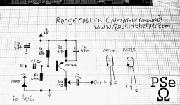
1704874878539.png

Here's the schematic from the website. See what I mean by "I want to flip it the right way"? That's easy enough to do in a drawing, but when I look at the veroboard I can't see what the difference would be. Positive goes to positive, negative goes to negative. And yet, something is still different. I need help understanding how to translate that difference to the veroboard.
 
What we're saying is that ground in the positive ground is not really ground. It's incompatible with real ground. So if you want to put it in the same box as the rangemaster - which in this case is regular negative ground - you need to make your fuzz with a negative ground too. Or you can do other more complex things but this is the simplest way.

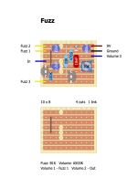
I redrew the Sabro layout for you as if you were using NPN Ge transistors. I would lay it out differently but that's irrelevant!


Fuzz.png

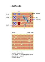
FWIW this is the Fuzz Face I would use:

Sunface Ge.png

I hope this helps! I left room in my Sunface layout to use transistor sockets so that you can experiment. It's almost always best to try a few different trannies in a Ge fuzz.
 
This also isn't what I am looking for, it is the opposite. I don't want to change the fuzz face; it doesn't work correctly that way. Oscillation happens. I want to change the specific Rangemaster vero layout I posted so it is a proper, positive ground, PNP using circuit that has no charge pump and no fuckery. Not looking for anything other than guidance on how to do that.

The vero layout I posted isn't an NPN layout, and I don't need an NPN layout; there are a bunch of those available. It is PNP laid out the wrong way so that it is powered upside down. I want to fix that. It's easy to do that in the schematic drawing I posted, and it's easy to visualize what to do on a breadboard. I don't know how to visualize the change on the specific veroboard RM layout that I posted.
 
Last edited:
When I read that, it feels like I'm not taking something into account.... bear with me.

Forgetting the diode (I put them on the power connector), I reverse the order of the caps and transistor, and the power leads. Aren't the resistors now connected to the wrong legs of the transistor? Do I need to account for that, and redraw the vero layout "mirrored"? Same question re: the pot, since when I flip the transistor but nothing else it's now tied to emitter
 
Back
Top