M800 Overdrive

music6000

Well-known member
Awesome JCM800 Emulation !!!
All the Trimmers were adjusted to 4.5v & it was meh, 4.75, 5v, 5.25v & 5.5v, Louder with no Gain!
Old School, Strummed a Chord & tuned each Trimmer by ear.
Critical Trimmer is the Tone trimmer, This effects overall EQ & gives it the Power of The JCM800 sizzle!
The Tone Trimmer is an Internal Potentiometer, It doesn't adjust the J201(Q4) below it, that has Fixed Voltage.

UPDATE - November 2019 : The J201's have been replaced with Siliconix J201's & are set to 4.5v.
It now has more Headroom & Sustain!!!


The JCM 800 label represents Jim's Number Plate, rumoured to be where the Amp got its name.
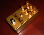
Delco JCM 800 Distortion Pedal 1.jpg

Delco JCM 800 Distortion Pedal 2.jpg

Here is a Good demo :
 
Last edited:
Nice looking build! Glad that adjusting the trimmers by ear unlocked the tone you were looking for.
 
Update : The internal Tone trimmer is just that, It adjusts the Low Mid to High End frequencies.
The J201 below it is separate & has fixed Voltage.
 
Hey! Having issues with mine, followed the wiring but I’m having ground issues. The switch I wired is wired differently than yours, why so?
 
I'm having issues with mine as well. Found the replacement PF5102 and J112 might be the culprit. I'm just waiting for my real 201 to show.
 
my j201s all work correctly, they all read well, I’m guessing the issues is the switch, got rid of the grounding. Clean sound on bypass but when I toggle it on it doesn’t work.
 
This is what I have used for years, Pedal PCB Footswitch wiring is correct & PCB matches the Footswitch breakout Board.
The one in the build instructions looks different to yours, the last row Is jumped, safe the middle one which is jumped with the input prong.
 
There is more than one way to wire a 3PDT stompswitch and get the same results. What Music6000 did is equivalent to the wiring diagram in the Build Docs.
 
M800 Latest Update : I revisited the pedal yesterday as I had recently acquired some Genuine NOS Siliconix J201 with the Dot.
I removed the Fairchild J201's & replaced with the Siliconix J201's.
I set them all to 4.5v except Q4 which has fixed voltage.
It worked instantly & Sounds better than before at 4.5V with even better sustain & more Headroom.
The Fairchild J201's had to be adjusted by ear as they were out of spec at 4.5v, remnants of what is left for the picking & the poor Receiver at the other end!
I have spoken to a few members that have been less than happy with their Build.

Chuck D. Bones has listed the specs that need to be measured to get maximum performance from the J201.

PedalPCB now offers the more stable SMD J201 & Adaptor Board pre soldered or as separate purchases.

This Pedal sounds Great but has to be with Genuine J201's that are in Spec with IDSS & VGS.
 
This Pedal sounds Great but has to be with Genuine J201's that are in Spec with IDSS & VGS.

I agree. I couldn't get it work with the substitutes. I wasn't expecting any better results from genuine J201, but I was completely wrong.
 
So what would be the ideal values (Vp / Idss) for the jfets in this? (paging Sir Chuck....)
 
It's subjective, but lower Vp will give more gain. With trimpots that large, any J201 that's in-spec should work. I'd use the lowest Vp parts for Q1, Q3 & Q6 because they have the smallest source resistors.
 
I knew you'd be right on it, thanks.
So (asking for a friend... ;) ) what do I measure to find out if my smd J201 that I banged already in there are a good choice and how would I (well my friend...) improve the biasing on that circuit?
 
Back
Top