SOLVED Mofeta bass and treble do nothing

frustrated

New member
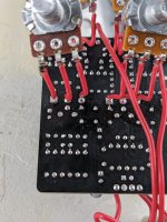
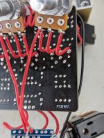
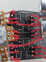
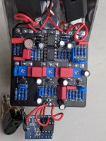
This is the second one I built, first one was perfect. My buddy liked it so much he asked me to build him one. It sounds good except the bass and treble controls do absolutely nothing. They 100% work on my first one. Measured the pots, they are working fine, I don't see any incorrect resistors, pretty sure the caps were all correct, some of them the markings are obscured by other components. Where should I look around? What went wrong?

Please and thank you.
 

Attachments

  • PXL_20230611_164524048.jpg
    PXL_20230611_164524048.jpg
    443.3 KB · Views: 52
Last edited:
Joints look dull—may be cold. The bottom side of the board would be more telling.

Are you getting output? Does the MIDS control work? The tone doesn’t have many parts—verify all parts and connections there.
 
Joints look dull—may be cold. The bottom side of the board would be more telling.

Are you getting output? Does the MIDS control work? The tone doesn’t have many parts—verify all parts and connections there.
They look weird because I've been poking them with multimeter leads and also it's lead free solder. I've reflowed several joints just to try but really the joints are all fine. I solder professionally under IPC certification.

Mid pot works, both gain pots work, volume works. Sounds awesome but I can't pitch this to my buddy with only partial functionality.
 
Last edited:
If the mids is working, maybe it has something to do with the caps going to the treble and bass pots. Or a cold solder joint on the pot lugs. Idk just a thought.
 

Attachments

  • IMG_6767.jpeg
    IMG_6767.jpeg
    141.3 KB · Views: 5
Are the pots that are under the PCB insulated from the PCB?
Define insulated? My pots are all connected to the board with insulated solid copper wire. I've measured the pots resistance and they check out. They are connected properly. They are not touching any part of the board if that's what you're suggesting.
 
Last edited:
A picture of the underside of the board would be helpful. There are a few pads that look like they have received quite a bit of heat (near the switch pads). I agree with @benny_profane that some of the joints look dull and could be cold.

It sounds like you need to audioprobe the circuit to find out where the issues are present and then we can go from there.

Also, where are your 2n5457 from?
All components came from Mouser. I pulled my LED out of the "A K" from the board because I realized with my Mas effects relay toggle it needed to be wired to that board. I think you're mostly just seeing flux.

Once again though, this is lead free solder which has different visual characteristics than conventional leaded solder. It can look flat rather than shiny and be a perfectly good solder joint. The irregular surface on the middle right A1M joints that everyone here seems to be crying about, and I've already mentioned this, is from poking the solder joints with a multimeter.

But sure, here's more pictures of the back of the board. It needs to be recleaned since I've reflowed a few joints and replaced two caps but I don't see any cold solder.
 

Attachments

  • PXL_20230612_195141791.jpg
    PXL_20230612_195141791.jpg
    435 KB · Views: 13
  • PXL_20230612_195213226.jpg
    PXL_20230612_195213226.jpg
    421.5 KB · Views: 13
  • PXL_20230612_195235372.jpg
    PXL_20230612_195235372.jpg
    427.7 KB · Views: 17
The irregular surface on the middle right A1M joints that everyone here seems to be crying about,
I'm not sure that that's an effective way to engage with folks who are trying to help you. Keep on like that and I doubt anyone is sticking around for you

The tone stack comprises C12, C13, C14, R11, and the three pots followed by the coupling capacitor, C15. Please verify that 1) the parts are correct and 2) you have continuity where appropriate. We can't see any values from the pictures you posted. We also can't visually confirm the integrity of your off-board wiring.


mofeta tone stack.png
 
Confirmed continuity between the mentioned components, C12, C13, C14, R11 and the respective pot lugs, every single lug, every single lead. Confirmed R11 is 56k. C12 is 270p ceramic, C13 and C14 are 22n film. What's next?
 
I don't have a spare 270p but I have a 390p, if C12 is the culprit would 390p be close enough to get it functional at least? I already replaced C13 and C14 with no effect. I measured R11 in circuit, it's about 56k. I don't know what else to try besides replacing C12.
 
It's more than likely there is a short or open connection somewhere rather than a problem component. Do the TREBLE and BASS pots have continuity with each other as they should? Something's missing.
Treble/Bass connectivity:
Lug 1/Lug 1: through the pots yes/full clockwise no
Lug 1/Lug 2: yes
Lug 1/Lug 3: yes
Lug 2/Lug 1: through the pots yes/full clockwise no
Lug 2/ Lug 2: yes
Lug 2/ Lug 3: yes
Lug 3/ Lug 1: through the pots yes/full clockwise no
Lug 3/ Lug 2: yes
Lug 3/ Lug 3: yes

This was checked with 200k resistance setting, my dinky home meter doesn't have the beeping continuity setting.
 
These are confusing. Are you turning the pot while measuring continuity? How does TREBLE lug 3 connect to BASS lug 3? Or is that a confirmation that the behavior is as expected?
 
These are confusing. Are you turning the pot while measuring continuity? How does TREBLE lug 3 connect to BASS lug 3? Or is that a confirmation that the behavior is as expected?
Probably because I have it on ohms, the diode setting doesn't show connection. I have a nice fluke at work, I can get a more reliable continuity check tomorrow. This thing is more for checking guitar pickup resistance.
 
Back
Top