
megatrav
Well-known member
I know this one knob fuzz is is based on the Alan Yee Fuzzy Nuts.
I can’t confirm the schematic but someone on Reddit said it’s a clone/modified Electra Distortion. I have no idea how credible that is.
This is the schematic I’ve found online, but if anyone wants to trace theirs I’d love to do one.
I can’t confirm the schematic but someone on Reddit said it’s a clone/modified Electra Distortion. I have no idea how credible that is.
This is the schematic I’ve found online, but if anyone wants to trace theirs I’d love to do one.

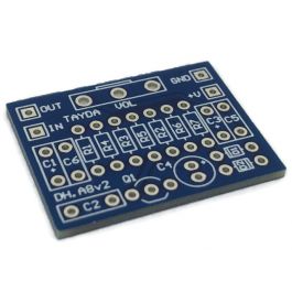

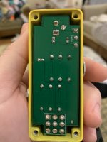
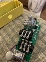
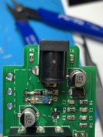
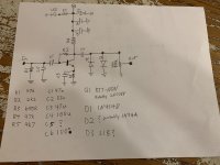

 . Also, if you give it a go please note the typo for R2. Should be 2M2 instead of 2K2.