Hello everyone!
I bought a Softii Overdrive Kit (PedalPCB) and after assembled I noticed that the Gain pot did nothing. It looked like it was always maxed out. I tested the pot and it looked like it was the flaw. When I had it all the way down (minimum gain), it would short in all the legs of the pot (I tested with a multimeter). When the pot was all the way up (maximum gain) it was only shorting in 1 pair of legs.
Since I wasn't going to use it in my current project and was expecting to do another order I waited and bought a new potentiometer. I changed the pot (tested it before putting in the pedal and it was fine (only shorted 1 pair in maximum and minimum)) and nothing changed. I return to test it (while it was soldered on the PCB) and it starts to happen what happened with the original pot (shorting in all legs).
I tested the original pot after replacing it (without being soldered to the PCB) and it is fine (only 1 pair in each time).
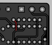
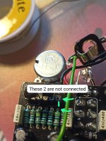
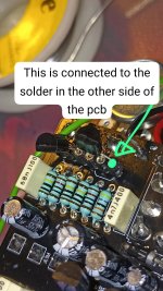
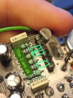
After looking at the board I noticed something: In the PCB, one of the legs of Q1 is not connected where it should be.
Since it's a bit hard to explain I'll attach some pictures:
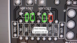
It looks like its missing on the board:
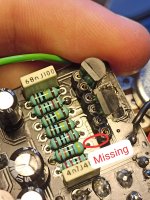
After seeing that problem, I made the connection myself. The pot is working now, but not fully. It changes the gain, but it's reducing clockwise which I think it's not supposed. Also, when in the stones mode (blue LED), when the gains is low it almost makes no sound... Video after fix: https://drive.google.com/file/d/1d1oCzM580ToH3mQ9GF_3RlHnC6sqrMiR/view?usp=sharing
It still doesn't seem right, and since I saw that defect in the Q1 I believe that maybe the board has other problems...
The only change I did was to use a footswitch instead of the original switch that comes with the pedal so I can change the mode while playing, but I don't believe that it affects the pedal in the way I'm saying...
After sending this information to musikding, it was passed to PedalPCB. The reply was that the connection that is missing is on the other side of the pcb and that I should contact PedalPCB directly (hence this post, I did not see a direct contact).
However, after being told that the connection is on the other side of the board I checked with a multimeter and it looks like there is no contact: https://drive.google.com/file/d/1LrhXNEvzhEZbHx-w81TK3P8gA_4xoikk/view?usp=sharing
This is everything I checked, any idea of what is going on? Since that in this last test it lookes like it doesn't make contact I still believe that something is wrong with the board.
Thanks in advance for reading.
Best Regards,
Fábio
I bought a Softii Overdrive Kit (PedalPCB) and after assembled I noticed that the Gain pot did nothing. It looked like it was always maxed out. I tested the pot and it looked like it was the flaw. When I had it all the way down (minimum gain), it would short in all the legs of the pot (I tested with a multimeter). When the pot was all the way up (maximum gain) it was only shorting in 1 pair of legs.
Since I wasn't going to use it in my current project and was expecting to do another order I waited and bought a new potentiometer. I changed the pot (tested it before putting in the pedal and it was fine (only shorted 1 pair in maximum and minimum)) and nothing changed. I return to test it (while it was soldered on the PCB) and it starts to happen what happened with the original pot (shorting in all legs).
I tested the original pot after replacing it (without being soldered to the PCB) and it is fine (only 1 pair in each time).
After looking at the board I noticed something: In the PCB, one of the legs of Q1 is not connected where it should be.
Since it's a bit hard to explain I'll attach some pictures:


It looks like its missing on the board:


After seeing that problem, I made the connection myself. The pot is working now, but not fully. It changes the gain, but it's reducing clockwise which I think it's not supposed. Also, when in the stones mode (blue LED), when the gains is low it almost makes no sound... Video after fix: https://drive.google.com/file/d/1d1oCzM580ToH3mQ9GF_3RlHnC6sqrMiR/view?usp=sharing
It still doesn't seem right, and since I saw that defect in the Q1 I believe that maybe the board has other problems...
The only change I did was to use a footswitch instead of the original switch that comes with the pedal so I can change the mode while playing, but I don't believe that it affects the pedal in the way I'm saying...
After sending this information to musikding, it was passed to PedalPCB. The reply was that the connection that is missing is on the other side of the pcb and that I should contact PedalPCB directly (hence this post, I did not see a direct contact).
However, after being told that the connection is on the other side of the board I checked with a multimeter and it looks like there is no contact: https://drive.google.com/file/d/1LrhXNEvzhEZbHx-w81TK3P8gA_4xoikk/view?usp=sharing
This is everything I checked, any idea of what is going on? Since that in this last test it lookes like it doesn't make contact I still believe that something is wrong with the board.
Thanks in advance for reading.
Best Regards,
Fábio


