Sunflower Fuzz Battery Mod

geadapedals

New member
Hello,

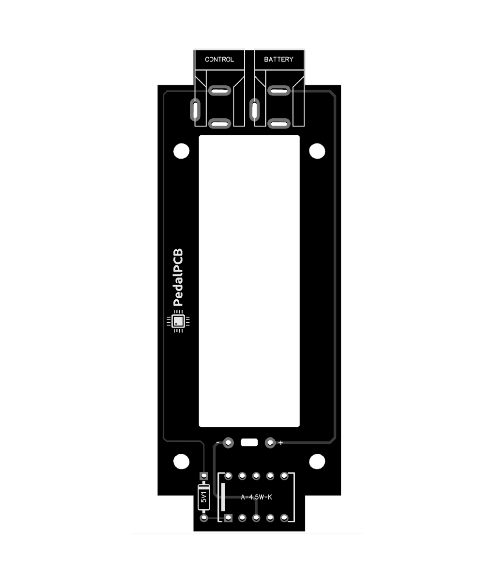
I'm building my first pedal, the Sunflower Fuzz, and did some research and basically everyone says fuzz works best with batteries, so I guess I will also do it.
I don't know anything about pedal building so I have no idea how to modify the pedal, so I was hoping someone could guide me on how to do it step by step like you would explain to a 5 year old 😅
Also came across a battery kill switch mod, I guess to increase the duration of the battery. Is it worth it? If yes, how can I do it?
Thanks
 
Negative wire of the battery snap to the Ring terminal of your input jack. This will disconnect the battery when nothing is plugged into the input.

If you aren't planning to include a DC jack then connect the positive wire of the battery snap to the + pad of the PCB.

If you are planning to include a DC jack you'll want one of the 3 terminal type, connect the positive wire to the Battery+ terminal of the DC jack.

Wire everything else up as normal.
 
Also came across a battery kill switch mod, I guess to increase the duration of the battery. Is it worth it? If yes, how can I do it?

Just to add, effects pedals are always powered on, even when bypassed.

If you don't wire it up to disconnect the battery when not in use the battery won't last very long.

One other option, you could build a battery box. This allows you to power the fuzz from a battery (contained inside the battery box) and will disconnect power whenever your pedalboard power supply is disconnected. If you plan for this fuzz to live on a board with other pedals it will prevent you from having to pull a cable from the fuzz every time you aren't playing. When your pedalboard loses power the battery will be automatically disconnected from whatever it is powering.

 
I built a battery only Sunflower when I was pretty new to all of this. This is the thread that got me started on it:

 
...
One other option, you could build a battery box. This allows you to power the fuzz from a battery (contained inside the battery box) and will disconnect power whenever your pedalboard power supply is disconnected. If you plan for this fuzz to live on a board with other pedals it will prevent you from having to pull a cable from the fuzz every time you aren't playing. When your pedalboard loses power the battery will be automatically disconnected from whatever it is powering.


@geadapedals
I'd like to note/upvote that this Battery Box Robert mentioned is even better than putting a battery on/off toggle-switch on the effect itself (for me), because I'm quite likely to forget to pull a plug or flick a battery-switch but way less likely to forget to turn off the power to the entire board.

YBLMV
(your battery life may vary).

Welcome to the forum!
 
Hi there!
I have now finished the pedal, but something is wrong.
When bypassed the guitar sound is normal as it should, but when I press the switch the amp makes no sound at all. The LED turns on and off when I press the switch btw.
Can anyone spot what's wrong?
Thanks pedal1.jpg pedal2.jpg pedal3.jpg pedal4.jpg
 
Sadly the TC chip is upside down! The semi-circle notch should be at the top (matching the pcb marking). It will be a challenge to desolder and save the chip, so you may need a new chip.

Desoldering also has the possibility of damaging the pcb by over-heating the pads around the hole. I generally use de-soldering braid, but it is difficult to clear the holes enough to safely remove the chip that way. Another option is a solder sucker.

I would likely cut the legs of the chip(ruining it), and use the Stainless Steel Desoldering Needles from stompboxparts. Apply heat with iron and gently push the terminals out with the needle, adding flux or more solder if it’s stubborn, then using the braid to clean the hole from remaining solder.

Others may use different desoldering techniques, what I put usually works for me with the least chance of damaging the pcb.

Final tip, use 8pin sockets for your chips, so it’s easy to flip if you make this mistake.
Damn... I didn't notice...
Should I desolder the pcb out of the enclosure first to work on the other side of the pcb?
 
Final tip, use 8pin sockets for your chips, so it’s easy to flip if you make this mistake.
Yes, these:


Using them also makes it possible to try different chips, that may or may not make an audible difference.
 
Damn... I didn't notice...
Should I desolder the pcb out of the enclosure first to work on the other side of the pcb?
What is it soldered to that's holding it in there? Just the power jack? I'd remove the pot hardware so the pots can just come right out and probably leave the wires connected to the board and see if there's enough slack in the wiring to flip the board over without de-soldering anything else. You can temporarily uninstall the footswitch and jacks if that helps.

If you can't get good access to the back of the board without de-soldering something, I would definitely recommend that you do so. De-soldering DIP packages can be a little frustrating even with full access to the board. I like to use desoldering braid for that process as well.

If I'm replacing a dead chip or one there's otherwise no reason to salvage, I've gone about it by cutting the pins as close as possible to the plastic IC body and then desoldering the pins from the board one-by-one. That's quite a bit easier IMO but you'd have to destroy the TC1044SCPA. Maybe something to keep in mind if you're struggling to remove it another way though.

There are other ways you can power that board by bypassing the TC1044SCPA section (though ideally it would be left in to keep things simple and neat-looking), so it will probably still be salvageable even if something goes horribly wrong, but I won't go into all the detail on that now unless you end up needing it, but I'd be happy to assist.
 
Just take your time getting it out. It can be frustrating but you should never have to *pull* on it. Maybe mildly encourage it, but don't pull. You'll rip a pad up, and it's especially easy to do with tiny PPcb pads(by biggest gripe, near only with ppcb).
And in all honesty, the IC possibly borked already, and will likely be borked before you get it out. Clip the leads, add flux on both sides and drop them out pausing between each one. Remember, your time is probably worth more than it's cost(especially if you have another on hand).
And don't push them out. Encourage them.
 
Back
Top