Sunflower Fuzz troubleshooting

CarloG93

New member
Hi people, this is my very first post here as I just completed my very first pedal build and, surprise, it does not work eheheh, so I'm hoping some of you can help me to identify the issue(s)
I picked up a sunflower Fuzz as I thought it might have been a good place to start. I have very little experience in soldering and none at building pedals.

Now, when testing the pedal the LED doesn't turn on.
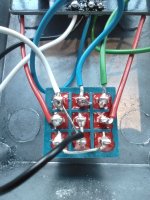
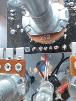
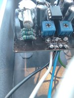
When the pedal il on, there is no difference in sound but the only thing I can ear is a tapping noise when the enclosure touches any other pedal on my board or when I press the switch so I'm guessing I also have a problem with the ground as it looks like is extremely microphonic.
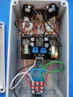
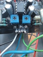
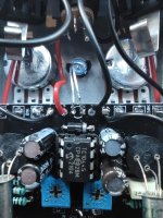
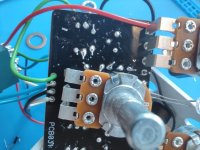
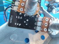
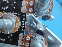
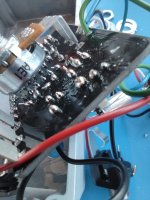
I'm attaching some pictures of my build (not for the faint-hearted, I think I've butchered the board) so you can maybe see where the problem might be. Are all the connections in the right place and is it just a problem of poor soldering skills or did I also put something in the wrong place?

Thank you in advance for your help, you are my only hope.

Cheers,

Carlo
 

Attachments

  • IMG_20210704_201650 copy.jpg
    IMG_20210704_201650 copy.jpg
    1.2 MB · Views: 45
  • IMG_20210704_201711.jpg
    IMG_20210704_201711.jpg
    400.2 KB · Views: 47
  • IMG_20210704_201739.jpg
    IMG_20210704_201739.jpg
    393.8 KB · Views: 40
  • IMG_20210704_201758.jpg
    IMG_20210704_201758.jpg
    417.4 KB · Views: 38
  • IMG_20210704_202028.jpg
    IMG_20210704_202028.jpg
    376.5 KB · Views: 31
  • IMG_20210704_202033.jpg
    IMG_20210704_202033.jpg
    396.3 KB · Views: 31
  • IMG_20210704_202038.jpg
    IMG_20210704_202038.jpg
    357.6 KB · Views: 40
  • IMG_20210704_202405.jpg
    IMG_20210704_202405.jpg
    377.5 KB · Views: 39
  • IMG_20210704_202418.jpg
    IMG_20210704_202418.jpg
    373.6 KB · Views: 39
  • IMG_20210704_202638.jpg
    IMG_20210704_202638.jpg
    381 KB · Views: 45
What voltage do you get to the pcb + and - pads

You do have a few ball like and dry looking joints and some of your connections look like there's not enough solder flow

I'd reflow your solder joints making sure you get a nice connection between solder pad and component leg / wire end, hold your iron on each joint for around 4 seconds until the solder flows

Remove your transistors and IC from their sockets when you do it to avoid heat damage

You don't want solder joints like in pic 8 ball like joints may be dry inside and indicate your iron temperature isn't correct

I run mine at around 400 degrees C and solder flows easily I clean and tin my iron tip every 2 joints or so
 
Last edited:
What voltage do you get to the pcb + and - pads

You do have a few ball like and dry looking joints and some of your connections look like there's not enough solder flow

I'd reflow your solder joints making sure you get a nice connection between solder pad and component leg / wire end, hold your iron on each joint for around 4 seconds until the solder flows

Remove your transistors and IC from their sockets when you do it to avoid heat damage

You don't want solder joints like in pic 8 ball like joints may be dry inside and indicate your iron temperature isn't correct

I run mine at around 400 degrees C and solder flows easily I clean and tin my iron tip every 2 joints or so
Hi there, thank you so much for the tips.
Yeah, I'm not happy either with my solder joints and I thought that might be the issue, I'll reflow the whole thing and try to get tidier e better joints. Would you suggest to reflow everything including the wires connections?

Also, I've measured the voltage on the pads and is around 6v. Please consider that I don't know much about electronic and I'm a complete amateur at this so I don't really know what that means ahahah

But thank you so much again for the help, I'll keep you posted once I do that and see what happens! 😉
 
Also, like you said, I did run my iron at around 400 °C and made sure that the tip was always clean and tidy. Is a pretty decent and new iron too so I'm pretty sure that it was only because of my poor soldering skills, but hey, it was my very first build so I was taking into account the chance that the pedal might not have worked at the first attempt. But I'm really hopeful that with the help from the forum I can make it work, and it will be very satisfying once I'll get it right ahah
 
Also the sundail pot doesn't look like it has a dust cover and could be shorting out on the solder tabs of the board when in the enclosure.

I think if you reflow those joints you might get some luck. Also need to bias the transistors. Do you have a multimeter? If so, put the red probe to a ground point like one of the drill holes in the enclosure and attach the black probe to collector pin of Q2 (right side pin) turn the BIAS trimmer until you get close to 5V. Clean trimmer set all the way CCW for full fuzz capabilities.
 
Last edited:
Also the sundail pot doesn't look like it has a dust cover and could be shorting out on the solder tabs of the board when in the enclosure.

I think if you reflow those joints you might get some luck. Also need to bias the transistors. Do you have a multimeter? If so, put the red probe to a ground point like one of the drill holes in the enclosure and attach the black probe to collector pin of Q2 (right side pin) turn the BIAS trimmer until you get close to 5V. Clean trimmer set all the way CCW for full fuzz capabilities.
Yeah I thought that at first, but when inspecting the pedal, the pot looks fairly far from the pcb, not sure what happens when in the enclosure. But thanks for pointing that out, I might install a dust cover just to be sure.

Also yes, I do have a multimeter and I was planning on biasing the pedal once I get it working ahah
 
Did you adjust the clean trimmer as @Many__Of__Horror says, depending on it's rotation it could affect your input signal

Try turning that

You'd need to bias it to get it to work correctly so I'd do that aswell

What are you using to power it 6v is low
 
Last edited:
  • Like
Reactions: fig
Did you adjust the clean trimmer as @Many__Of__Horror says, depending on it's rotation it could affect your input signal

Try turning that

You'd need to bias it to get it to work correctly so I'd do that aswell

What are you using to power it 6v is low
I didn't adjust the trimpot as I assumed the pedal isn't working as the led does not turn on. But the thing is that when the pedal is engaged I get signal going through (the normal guitar signal as the pedal was not there, no drop or increase in volume either, just the pure guitar signal as I would get by plugging the guitar straight into the amp, and no change in sound when turning the knobs whatsoever). I'll try that once I get back home.
Also I'm not too sure about the value I read this morning because I measured it in a rush while I was getting ready to go to work ahah
 
If the volume control doesn't affect the level when the effect is "on" you most likely have a wiring or switch issue.
I see, I'll double check my connections!

So what's your opinion guys? What are the steps I should follow before starting to reflow the whole thing, starting from adjusting the clean trimpot?
 
I see, I'll double check my connections!

So what's your opinion guys? What are the steps I should follow before starting to reflow the whole thing, starting from adjusting the clean trimpot?
I would re-flow the board as step 1. You need less solder than you think. I’d also check that everything is soldered. At least one of the jack grounds, as well as the power negative look like they are barely soldered in, if at all. I would then make sure that the one pot isn’t touching anything when installed. Also, you should be measuring close to 9 volts at the jack, yet you said you measured 6v at the pads? I would check again. If your measurement is true, I think there is an issue there.

I have a stack of pedals that I’ve never been able to get working. There is still time, though. Take your time and double check everything. There’s no rush. It will still be broken tomorrow…
Nice one, thanks so much for the Input man and everybody here. I'll do it all, starting from making better solders and see where it goes, and I'll keep you posted along the way!
 
What type of power supply are you using just to make sure it's the correct type

Are you saying you get clean signal in both positions of the 3PDT switch effect and bypass
 
What type of power supply are you using just to make sure it's the correct type

Are you saying you get clean signal in both positions of the 3PDT switch effect and bypass
Yes, I get clean signal when the pedal is of and engaged as well.
I'm using standard 9v DC, from my harley benton powerplant ISO 12 pro
 
That's ok

Check what voltage you get on the DC jack lugs and both sides of D1 if you're only getting 6v it's just to see where it drops out, anode + side of D1 you should get whatever's coming out of your power supply, cathode - side of D1 just a little less with the voltage drop through the diode around 0.3v less

You can check what power is coming out of your power supply by putting your ground black probe in the centre and red probe on the sleeve or outer part with your meter set to 20v DC like this

20200614_164742_copy_251x415.jpg
 
Last edited:
That's ok

Check what voltage you get on the DC jack lugs and both sides of D1 if you're only getting 6v it's just to see where it drops out, anode + side of D1 you should get whatever's coming out of your power supply, cathode - side of D1 just a little less with the voltage drop through the diode around 0.3v less

You can check what power is coming out of your power supply by putting your ground black probe in the centre and red probe on the sleeve or outer part with your meter set to 20v DC like this

View attachment 13312
So I came back home and measured everything better. The power supply measures 9.25v and the + & - pads of the PCB 9.25V as well, so it does the anode of D1, still 9.25V. The cathode of D1, on the oder hand, shows 0.11V
 
If you haven't already try reflowing D1 cathode solder joint

It shouldn't be dropping that much voltage through it

The 1N5817 datasheet has the typical forward voltage listed as 0.25v so you'd expect around 9v on the cathode

Possibly a dry solder joint, faulty diode or somethings putting a heavy load on it

Where did you get your 1044 IC
I started reflowing the whole board yesterday evening, including all the wiring. Hopefully better joints will solve the issues.
I got the board and all the components as a full kit from a shop in Germany, as I live in the UK it was the most convenient option for me
 
As @Coda says there's no rush take your time

We all initially go mad if it doesn't work first time or maybe it's just me, but hopefully you'll learn a few things from the good folks here

It's not a particularly complex circuit

It sounds like you're getting no power to the circuit beyond D1

My normal approach is to check voltages 2 or 3 times as you have then double check by moving onto the next component so if you're getting 0.11v on D1 anode you should get the same on IC pins 1 and 8

Quite often you'll get a poor connection with your meter probes hence I do it a few times to make sure like you did with your power reading

Using a schematic is very much like join the dots

Post your IC1 voltages they may reveal something pin numbers like this

20201124_153036.jpg
 
Back
Top