The Gent - No Effect

dontstaylong

New member
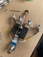
Hey all. Third build from the site, and naturally running into more issues. I am pretty sure I’ve messed up the wiring here, but I’m not sure where.

When it’s plugged in, I’m getting clean signal through it, but nothing once the switch is pressed. Is my (ugly, hacky) workaround with the 3pdt breakout board the issue?
 

Attachments

  • DFD9A505-0BAF-4C4E-9A91-3697C1273080.jpeg
    DFD9A505-0BAF-4C4E-9A91-3697C1273080.jpeg
    584.5 KB · Views: 54
  • D6B3B82A-F57E-4088-A085-50DAE6504BF8.jpeg
    D6B3B82A-F57E-4088-A085-50DAE6504BF8.jpeg
    486.4 KB · Views: 54
Your power is connected to the wrong lug, it needs to be the outside one leaving the middle empty. Also splicing wires is a recipe for issues. Always run one continuous wire.

Once you fix the power jack try it again and see if your led comes on ( mark sure it’s not grounding against something when you do power it.
 
I am a novice with all this stuff, including figuring out how to use a multimeter, but I’m getting 0v reading across all the 1B5817s I got from Tayda. Does that mean it’s a bad batch?
Likely means there’s so thing wrong with your power supply, dc jack or wiring. Your multimeter should be set to DC voltage anything at or above 9v. Even with a bad batch of diodes, you’d have voltage on the anode side:
 
Changed out the DC jack with a different one, and it’s blowing LEDs when I power it on. Still no effect signal either, with both pots completely open. It’s the same 9v power supply chain I use for all my other 9v pedals.

Other than the spliced wires, what am I doing wrong?

I was hoping to build 3 of these but even getting one working is proving difficult!
 

Attachments

  • image.jpg
    image.jpg
    503.7 KB · Views: 28
  • image.jpg
    image.jpg
    467.8 KB · Views: 28
DC Jack was addressed by CarlinB in post #3 and OPer has changed it in post #6 — it looks correct.

Some of the solder joints look like they could be reflowed.

+1 To Jimilee's Audio Probe suggestion, and Carlin's suggestion to have one continuous wire from jacks to 3PDT.


I'll suggest socketing the transistor in future; I've never had a problem with just socketing transistors, but other people have so if you're worried about socketing then once you establish a transistor works you can tack-solder one of the legs to the socket so it won't fall out.
 
Another Note, are you plugging your input and output into the correct jacks? I've found myself puzzled to why a circuit doesn't work only to realize that with it out of the box I plugged in the output and input backwards. You will still get bypass, but certainly no sound when you fire it up.
 
Another Note, are you plugging your input and output into the correct jacks? I've found myself puzzled to why a circuit doesn't work only to realize that with it out of the box I plugged in the output and input backwards. You will still get bypass, but certainly no sound when you fire it up.
This just about made me have a heart attack, but unfortunately, nah still doesn't work right.

Reflowed everything today and still no dice. Working on the second build of the group to just see if it's a fluke.

I'll start working on an audio probe as well, sounds like a good idea in general.

Re: the 3PDT switch wiring - I realize I goofed up and got the basic breakout board, even though the PCB only has through holes for 4 wires instead of 6. Is that likely the cause, or have I guessed at the right workaround for wiring?
 
Back
Top