You are using an out of date browser. It may not display this or other websites correctly.
You should upgrade or use an alternative browser.
You should upgrade or use an alternative browser.
The Perfect Treble Boost - Help me build it!
- Thread starter daeg
- Start date
daeg
Well-known member
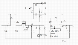
Let me walk through it.
The Buffer, Transformer and 'Edge' control are all there to counteract the shrillness you get when putting a Rangemaster downstream from a buffer.
- We're only using half of the Transformer, so it behaves as an Inductor to 'simulate' the response of guitar pickups. It's far from accurate simulation, but it gets the job done. Read More.
- The switch allows you to switch between half and full inductance, which moves the resonant peak and corner frequency of high rolloff. AMZ describes it like a single-coil vs humbucker response, and that isn't a huge stretch either.
- 'Edge' is your tone control that goes from icepicky highs clockwise to dulled highs counterclockwise. It's interactive with the transformer as well as the low-Z HPF circuit that follows it, but since we're making analogies, think of this as your cable length.
A couple of changes have been made to the RoG Omega as well.
- The 'Clarity' control gradually allows a Ge diode clip the signal. Turning it counterclockwise adds some reminiscence of a the grittyness of a Germanium Transistor if you're looking for that. The clipping is asymmetrical and unfiltered. It loads the Transistor, limits headroom a bit and _does not_ sound like an overdrive. Turning it fully clockwise gives you the loudest, most clear, punchy signal. You'll be surprised how well it works. (Check out the Electrosmash article to see how the original unit gently clips.)
- The added trimpot (R8) is a nice-to-have. It helps you fine-tune the output of Q2, while changing the bias point of Q3. At center there is no change from the original circuit. Adjust to taste to make your circuit a little hotter or cooler.
daeg
Well-known member
So have you breadborded this or built it already and how does it sound?
It's on bread board right now and think it sounds great.
Of course, Rangemasters do not sound good on their own, so their 'sound' revolves how well they get along with your guitar and already distorting amp.
daeg
Well-known member
So, I created the thread because... my building skills suck.
Before PedalPCB, I mostly used perf, my own layouts and things were always... messy. Things would work for a few months then start getting intermittent issues, often have noise problems, yet I was too stubborn to buy PCBs.
Now I'm ready to assemble this thing, but ... how should I put this all together?
BurntFingers
Well-known member
Easy, layout the PCB and get it made. Jlcpcb will do you 5 for $2.
Chuck D. Bones
Circuit Wizard
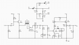
That INDUCTANCE switch is not wired correctly. If you short a winding, or any part of a winding in a transformer, the inductance goes down to nearly zero. You can use the switch to select between full winding and 1/2 winding. With half of a the winding, the inductance is not cut in half, it's divided by four. That's because inductance is proportional to the square of the number of turns. Not the same as tapping a Humbucker because the coupling between the bobbins is nowhere near 100%.
Not sure that Ge diode does anything. The way you have it facing, it will never go into forward conduction. If you turn it around, it will always conduct.
Thanks for pointing me to the ROG Omega. I thought I had all of their schematics, but that one got past me. Gotta build me one o' dem!
Not sure that Ge diode does anything. The way you have it facing, it will never go into forward conduction. If you turn it around, it will always conduct.
Thanks for pointing me to the ROG Omega. I thought I had all of their schematics, but that one got past me. Gotta build me one o' dem!
daeg
Well-known member
daeg
Well-known member
daeg
Well-known member
Easy, layout the PCB and get it made. Jlcpcb will do you 5 for $2.
Taking a look at this. I had no idea this was so affordable.
I've wasted so much time making perf layouts and builds that never hold up.
Any recommendations on how to get started?
Chuck D. Bones
Circuit Wizard
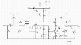
Good eye Chuck. It most definitely does work... I just forgot to put the capacitor on the schematic. Fixed it.
View attachment 7382
Let me know if that works, because the only way for C6 to get any charge on it is from D1's leakage current. You might need to put a resistor in parallel with D1 to ensure there is enough leakage current. Something like 100K maybe.
daeg
Well-known member
Just tried it. The 100k resistor definitely makes a difference -- lower headroom, more squashed.Let me know if that works, because the only way for C6 to get any charge on it is from D1's leakage current. You might need to put a resistor in parallel with D1 to ensure there is enough leakage current. Something like 100K maybe.
I might yet prefer it without, as it cuts less volume and is more of a crackly grit as opposed to a squished farty sound. I'll play with it on breadboard for a few days.
BurntFingers
Well-known member
Taking a look at this. I had no idea this was so affordable.
I've wasted so much time making perf layouts and builds that never hold up.
Any recommendations on how to get started?
I use eagle for the schematics and for PCBs, then just export the gerber files as a zip which is uploaded to jlcpcb. 2 weeks later I have the PCBs.
Any software that allows exporting of gerber files is all you really need. I think pedalpcb uses diptrace.
Nostradoomus
Well-known member
Yeah DipTrace is pretty slick and newbie friendly.
Nostradoomus
Well-known member
Download the rullywow DipTrace library, it’s got enclosure outlines so you can size your board cutout properly.
Robert
Reverse Engineer
Anyone have templates for PedalPCB-esque boards (125B, top-mounted jacks)?
I don't use a template, each one is created manually.
For a 125B using the standard drill template here you can go to up 2.35"W x 2.4"H, assuming the lugs for the top row of pots is 0.125" from the top edge of the board. This puts the board right against the edge of the 3PDT.
daeg
Well-known member
I don't see it on the Rullywow site. Could you point me to it?Download the rullywow DipTrace library, it’s got enclosure outlines so you can size your board cutout properly.
Similar threads
- Replies
- 24
- Views
- 638


