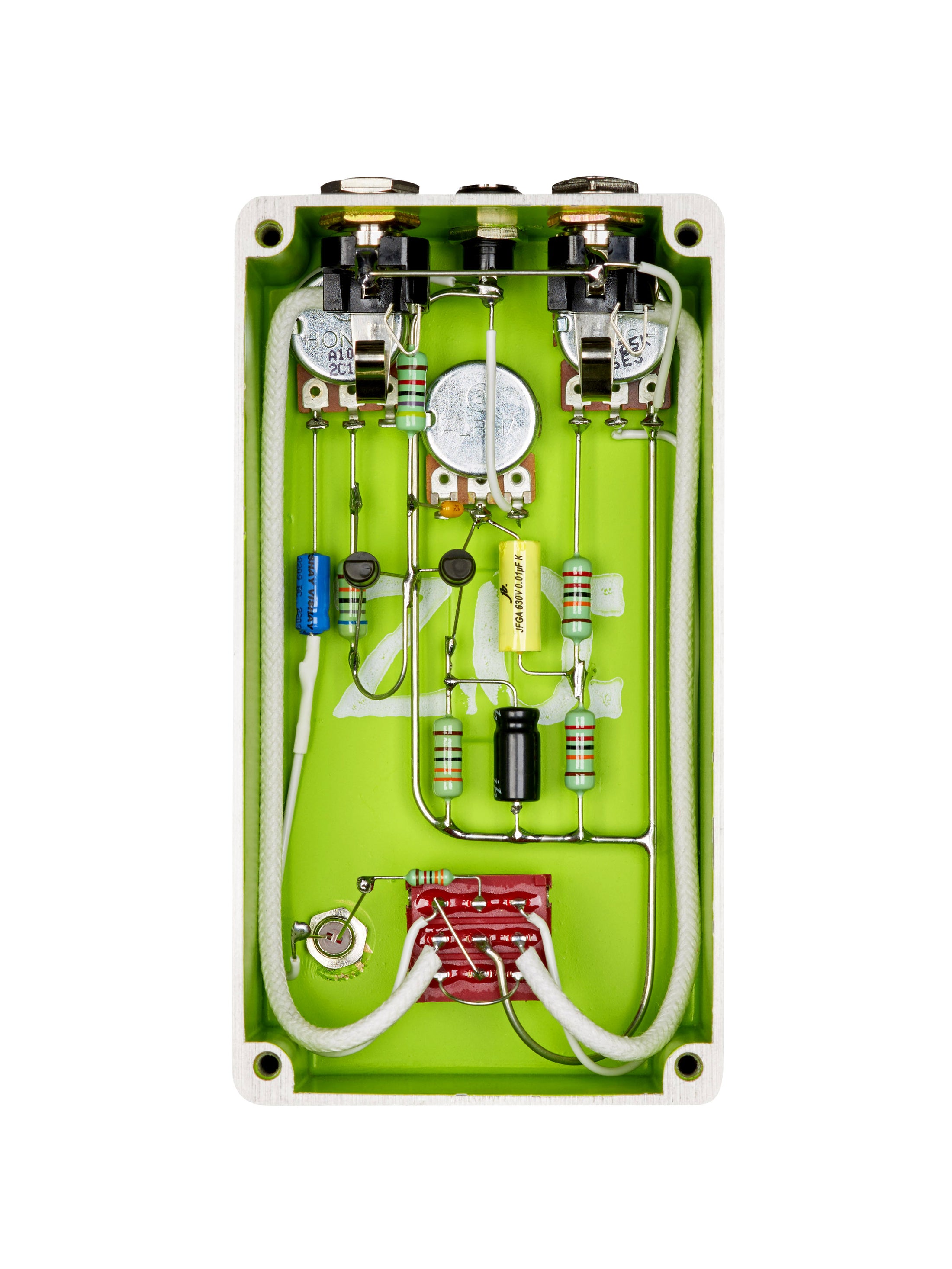
Note that although the circuit looks like a FF at first glance, the fact that it's lacking the global feedback (through the 100K resistor in the FF) is noteworthy. Q1 is biased with local collector feedback instead. Also, there is typically a pulldown resistor (470k) at the input although schematics often do not show it (the one in OP's post does not), and it's often hidden fairly well in gut pics. You can see it coming off of the same footswitch lug as the 10u input electrolytic in the pic
@Bricksnbeatles posted. It just goes from there to GND.
The optional 3k9 resistor will change the bias of Q2, so you may try temporarily jumping one in when you swap out Q2 to see how it sounds with and without.
The 2M2 resistor definitely is odd - it's also in the Mk1 and Zonk Machine (original). The 2M2 resistor with 500K divider reduces the max output to a little less than 20% of what it would be without the divider. It does quiet the output, but IME it should be capable of getting plenty loud still. But yes, people do remove it or lower its value fairly often in modern builds. As far as why it's there - just speculation, but I have two theories:
1) The Mk1 is a modified FZ-1, and the Zonk Machine (original) is nearly identical to the Mk1. The FZ-1 does not have the 2M2 resistor, so it may have been added to the Mk1 in an effort to keep the output more in line with what you'd get from the 3V-powered FZ-1, and it was either just left in or similar logic was used for the Zonk/Zonk II.
2) It's easy to miss, but the volume pot is wired strangely (lugs 2 and 3 reversed from what is normal) in both the Zonk Machine and Zonk II, and the early Tonebender Mk1(s) (stripboard version) supposedly had this same wiring. My guess is that the odd pot wiring is done to limit the effects of the volume knob when bypassed, and the 2M2 resistor is there to limit the loading of the circuit when bypassed, as the Zonks were NOT true bypass (I'm unsure if the early Mk1s were, later ones with standard volume pot wiring DID use true bypass). The Zonk's footswitch basically connects the input jack to either the actual input jack location drawn in OP's schematic or lug 3 of the volume pot (common with the output) depending on footswitch position. With the effect bypassed, lug 3 of the volume pot is still connected to the signal path. The 2M2 resistor limits the loading effect of the rest of the circuit, while the unusual pot wiring ensures that there is always ~500kΩ to GND from the pot which will have minor loading effects.
However, if the pot was wired normally, there would be a variable resistance to GND (the resistance between vol pot lugs 1 & 2) depending on the volume knob's rotation. With the volume knob turned all the way down, the signal would be shunted to GND even when the effect is bypassed. This is less-than-ideal on its own, but it was compounded in the original Zonk Machine by the fact that it has a battery disconnect on the volume knob, so having the volume turned all the way down when disengaged may be fairly common with these pedals.
Lastly, I've heard anecdotally that removing/lowering it can add some brightness. I'm guessing that's from its interaction with parasitic capacitance of cabling etc. forming a subtle low pass filter. Probably not a design intention, but maybe something to keep in mind.