
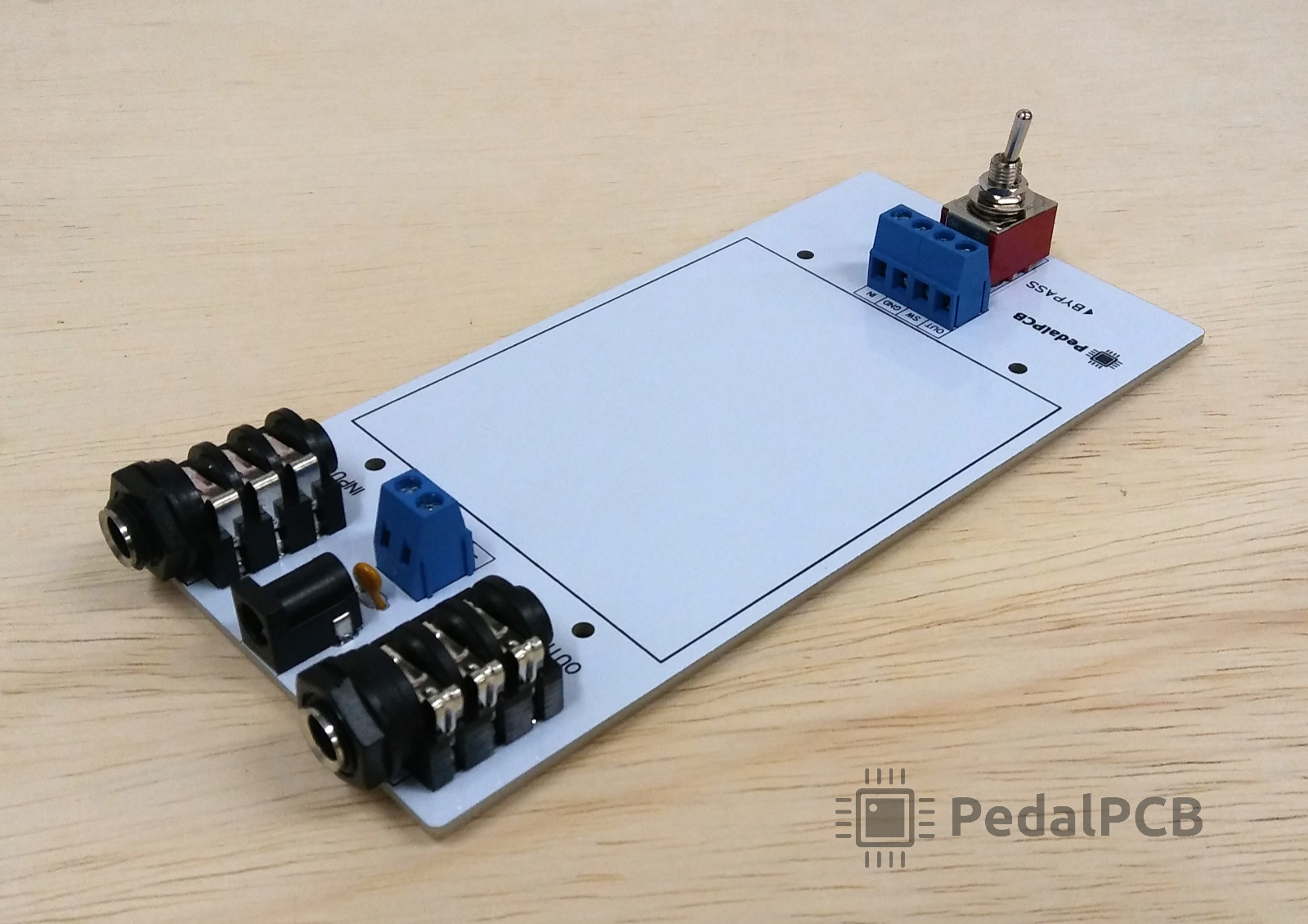
So I’m not sure what to do with the switch. I’ve got all the other pieces soldered on, and I’m working on my first build, but not sure how to test with the switch. Do I even solder the switch in? Doesn’t look like there’s much space with the holes on the pins. I imagine I’ll wire from the board to + - in, out, etc into the blue pieces, but not sure.
Is it possible to test the Platform by straight up instrument to platform to amp? Any pictures detailing these connections? The one other thread with a setup pic isn’t very clear and doesn’t show the switch
Is it possible to test the Platform by straight up instrument to platform to amp? Any pictures detailing these connections? The one other thread with a setup pic isn’t very clear and doesn’t show the switch


 Mwah
Mwah  mwah
mwah  mmmwwwahhh !

