Best software for making drill templates?

Kroars

Well-known member
Hello All,

Hope the PedalPCB family is doing well. I recently came across some pcbs that don’t offer drill templates (Moone Electronics) and thought, rather than to draw/measure free hand, there’s got to be software (or something) available to do just that. I’m not great with computers, though I have a decent laptop. So, it would need to be very user friendly, preferably straight and to the point (not too in depth) just for making/saving drill templates. To give you an idea of my inadequate computer skills, I purchased a silhouette vinyl machine to make labels/small graphics for my pedals, although once I realized the in depth nature of the software required -I set it aside and haven’t used it once. There’s a couple hundred down the drain…. Well, I plan on figuring it out someday, but it seems one almost needs a degree in graphic design in order to take full advantage of the softwares offerings….

Anyway, back to drill templates. I don’t suppose anyone could point me in the correct direction to some software/app or so on that will be easy to use, and have the ability to create/save/printout various drill templates.

Thank you kindly!
 
Do you plan on measuring the pcbs and transferring those measurements onto a drawing or cad program?(That's sort of what I'm imagining.) And then, mainly printing them out, and using the prints as a drilling template; at least, not at this initial point wanting to have a file that could be sent to a CNC machine.

I can't make specific recommendations; most of the graphics programs that I'm familiar with (CAD and otherwise) do have a definite learning curve to them. But some are much easier, and your needs are really basic. You basically just need to draw a few basic shapes (rectangles, circles, lines), get them located where you want them, in whatever alignment that you intended.

You realistically only need to learn a very basic subset of the software, no matter how complicated it is. In this regard, having ether a teacher, or a company with excellent videos or an active forum, might be best to help you overcome your concerns, and point you to the specific bits you need to learn. If no one else chimes in, ping me, and I'll do a bit of a "simple drawing app" search for you. Do you use a mac or a PC?
 
I have done this many times over the years. The easiest way I have found is to use vector based graphic software such as inkscape, affinity designer or illustrator and use the pedal vector pack. It includes hardware, enclosures and printable drill templates to make your own templates. I like to see that everything fits without issue, I can't say that about every vendor I've bought from over the years 😑😂
 
Would learning the SVG syntax be something you’d feel comfortable doing? https://www.w3schools.com/graphics/svg_intro.asp

You could create drill templates as text editor created svg files - the svg standard accepts inches and mm among other units that can be used. Most tutorials will show (essentially) pixels as the default unit but for your use it’d be pretty straightforward.
 
Last edited:
Like Alan mentioned there are learning curves to just about all of them. I've been testing some out just to do basic stuff like import drill templates and size knobs out, label pots, add graphics, etc. For, me I found Inkscape to cover a lot of areas. It's free and there are a ton of videos and other resources out there. Even with that it's still not super intuitive. I've also tried GIMP and Paint.net and still found Inkscape to be the most relatively user friendly.
 
In your specific case I would hand draw the templates, valid the template, take measurements, scan in your template, use software like coreldraw to "trace" the drawing and adjust measurements as needed.

Alternatively you could use cad software like mentioned to make it without the "tracing".

Also look into kicad/eagle enclosure templates. I found those have associated vector graphic files that can move between imaging software to use as a base.

You may be able to import an already made pdf template from somewhere and modify that to be like your hand drawn template. (this is what I did for my thetonegeek ts10 enclosure graphics).
 
In your specific case I would hand draw the templates, valid the template, take measurements, scan in your template, use software like coreldraw to "trace" the drawing and adjust measurements as needed.
That's a very good idea.
 
Would learning the SVG syntax be something you’d feel comfortable doing? https://www.w3schools.com/graphics/svg_intro.asp

You could create drill templates as text editor created svg files - the svg standard accepts inches and mm among other units that can be used. Most tutorials will show (essentially) pixels as the default unit but for your use it’d be pretty straightforward.

I’ve been wanting to make an online designer and/or drill guide.

I made this a couple of years ago when I was rewiring my old Honda:
 
As a manufacturing/distribution/analytical software developer, retired, and a graphics software user I can say just about everything is going to have about the same learning curve.

You're going to need to be able to transfer measurements of a metal rectangle to a drawing of a rectangle, and then place circles on that drawing. Most people usually use a small dot in the middle for the center of the drill, with an outline of the outside of the hole and either colored by size or labeled 3/8" (etc) under the large circle.

With many packages, you can set the bottom left of the rectangle as 0,0 and then click on the proper size circle, and type in 1.5,2.5 and it'll plop the circle at exactly 1.5" horizontal and 2.5" vertical from 0,0.

Since you don't know any drawing packages yet, and Inkscape is free and several people here can help you, I'd say start with that. There is more than likely an Inkscape forum where more advanced things can be asked and answered as well.

I prefer Microsoft Visio, but it has a HEFTY price tag. I usually buy 6-7 year old software to save money - the only time I had a new version the company I worked for paid for it.

I've been using Visio and Coreldraw since the 90's when they were version 1. Inkscape is very VERY much like Coreldraw, around version 8. I think my company paid about $300 for that in 1990's currency.

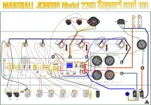
I build amps and use Visio for the layouts of the wiring as well as hole placement for the chassis:

JCM800 M2203 100W Triagon.jpg
 
Last edited:
As a manufacturing/distribution/analytical software developer, retired, and a graphics software user I can say just about everything is going to have about the same learning curve.

You're going to need to be able to transfer measurements of a metal rectangle to a drawing of a rectangle, and then place circles on that drawing. Most people usually use a small dot in the middle for the center of the drill, with an outline of the outside of the hole and either colored by size or labeled 3/8" (etc) under the large circle.

With many packages, you can set the bottom left of the rectangle as 0,0 and then click on the proper size circle, and type in 1.5,2.5 and it'll plop the circle at exactly 1.5" horizontal and 2.5" vertical from 0,0.

Since you don't know anything yet, and Inkscape is free and several people here can help you, I'd say start with that. There is more than likely an Inkscape forum where more advanced things can be asked and answered as well.

I prefer Microsoft Visio, but it has a HEFTY price tag. I usually buy 6-7 year old software to save money - the only time I had a new version the company I worked for paid for it.

I've been using Visio and Coreldraw since the 90's when they were version 1. Inkscape is very VERY much like Coreldraw, around version 8. I think my company paid about $300 for that in 1990's currency.

I build amps and use Visio for the layouts of the wiring as well as hole placement for the chassis:

View attachment 50121
Where do you get the “parts” you use in Visio?
 
Where do you get the “parts” you use in Visio?
I get most of my components from www.cedist.com, which is wholesale. If you have a business license they'll add an account for you. Most of my resistors I bought 20 years ago from Newark when they were having a clearance sale. I literally have about 40 pounds of 1w and 2w carbon film resistors, some of which were like 20 for a penny. Now that's a sale!!!!

Oh, wait, you mean where did I get the illustrations of the components? I drew them. I've been using graphics software for 30 years.... I can really draw well. I measure these suckers with calipers so they are accurate down to the 100th of an inch.

Drew these too, all in vectors:

My monogram:
Elwood Monogram.jpg
My drawing for my Klon pedal:
My Klon Centaur.jpg

This was done in Glasseye, a stained glass design tool
1686187521215.png
 
I get most of my components from www.cedist.com, which is wholesale. If you have a business license they'll add an account for you. Most of my resistors I bought 20 years ago from Newark when they were having a clearance sale. I literally have about 40 pounds of 1w and 2w carbon film resistors, some of which were like 20 for a penny. Now that's a sale!!!!

Oh, wait, you mean where did I get the illustrations of the components? I drew them. I've been using graphics software for 30 years.... I can really draw well. I measure these suckers with calipers so they are accurate down to the 100th of an inch.

Drew these too, all in vectors:

My monogram:
View attachment 50130
My drawing for my Klon pedal:
View attachment 50131

This was done in Glasseye, a stained glass design tool
View attachment 50132
Wow, nice art. And yes, that’s what I was referring to, the drawn components, very nice there too.
 
Wow, nice art. And yes, that’s what I was referring to, the drawn components, very nice there too.
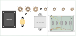
I just drew the top side of the tube sockets a couple nights ago, I'm particularly pleased with the results! This is the top of a Tremolux 6g9b which is the 1962 version of the Blond Tremolux. It has the tremolo tied into the bias of the tubes so the tube power is adjusted for the effect, instead of an oscillation on the volume. But I'm laying it out on a Hammond 17x8x3 instead of that HUGE freaking chassis that Fender used.

1686191579551.png
 
Do you plan on measuring the pcbs and transferring those measurements onto a drawing or cad program?(That's sort of what I'm imagining.) And then, mainly printing them out, and using the prints as a drilling template; at least, not at this initial point wanting to have a file that could be sent to a CNC machine.

I can't make specific recommendations; most of the graphics programs that I'm familiar with (CAD and otherwise) do have a definite learning curve to them. But some are much easier, and your needs are really basic. You basically just need to draw a few basic shapes (rectangles, circles, lines), get them located where you want them, in whatever alignment that you intended.

You realistically only need to learn a very basic subset of the software, no matter how complicated it is. In this regard, having ether a teacher, or a company with excellent videos or an active forum, might be best to help you overcome your concerns, and point you to the specific bits you need to learn. If no one else chimes in, ping me, and I'll do a bit of a "simple drawing app" search for you. Do you use a mac or a PC?
Yes, that’s exactly it. I figured I’d measure the controls on the pcbs and transfer to some sort of program that can save/print out templates. At the end of the day, I’d like to be able to have a result similar (if not more crudely similar) to the drill templates on the PedalPCB build docs. I can then start a thread here and include them as attachments for others to use as well.

I’ve got a standard PC, maybe a couple years old at this point. Looks like I’ve got a lot of great responses to go through. May be able to get this to work out after all! Thank you kindly!
 
As a manufacturing/distribution/analytical software developer, retired, and a graphics software user I can say just about everything is going to have about the same learning curve.

You're going to need to be able to transfer measurements of a metal rectangle to a drawing of a rectangle, and then place circles on that drawing. Most people usually use a small dot in the middle for the center of the drill, with an outline of the outside of the hole and either colored by size or labeled 3/8" (etc) under the large circle.

With many packages, you can set the bottom left of the rectangle as 0,0 and then click on the proper size circle, and type in 1.5,2.5 and it'll plop the circle at exactly 1.5" horizontal and 2.5" vertical from 0,0.

Since you don't know any drawing packages yet, and Inkscape is free and several people here can help you, I'd say start with that. There is more than likely an Inkscape forum where more advanced things can be asked and answered as well.

I prefer Microsoft Visio, but it has a HEFTY price tag. I usually buy 6-7 year old software to save money - the only time I had a new version the company I worked for paid for it.

I've been using Visio and Coreldraw since the 90's when they were version 1. Inkscape is very VERY much like Coreldraw, around version 8. I think my company paid about $300 for that in 1990's currency.

I build amps and use Visio for the layouts of the wiring as well as hole placement for the chassis:

View attachment 50121

Thank you for the in depth response. I’ll check out Inkscape and see what I can come up with. That’s exactly what I was looking for, thank you!!
 
Back
Top