Electrovibe

So, armed with the above comments from @PedalPCB, my multimeter and the Speed breakout board, I did a little research and continuity checking.

The center switch on the Speed board has the top most lugged tied to the center and connecting to ground through the pad on the main board.

I popped a switch in the breakout board to check whether leaving these 2 pads unsoldered on the board would allow me to bypass the integrated jumper trace. Other than normal switching continuity, there was never continuity between pads due to the integrated jumper. This is good news with respect to using a bicolor LED!

So here is how I see this going:

1.) Install 1/2 of the Bi LED as normal. The common anode makes connection on the main board to power and one of the cathodes makes connection to the bottom lug of the center switch as normal.

2.) Leave the top and center lugs of the Speed switch unsoldered on the breakout board. This nullifies the integrated jumper. Use the main board ground pad on the Speed switch rail to run a wire to the center lug of the center switch.

3.) Attach a wire to the remaining Bi LED cathode and attach it to the top lug on the Speed switch center switch.

This should look very clean as the wires can be hidden under the Speed switch breakout board. You simply have to suss out which color corresponds to what Speed control.
If one doesn't solder those two footswitch lugs to the breakout board isn't it possible that they still make contact with the pads?
 
Double checked my bom from Mouser and it's the:

M2012TNW01-DC
NKK Rocker Switches
US HTS:8536509065 ECCN:EAR99 COO:CN

I have to admit though that I'm always nervous ordering from Mouser for odd stuff like this cuz I usually goof it up. This one was a winner though.
 
Light shield is nice for the setup but once it's closed up you should be good. Man, that's a great job. I love the red knobs and the way the red/black theme carries over to the inside. Nicely done!
 
That’s a slick idea. Although, I’m sticking with the breakout board because I’m using pin headers to eliminate the hookup wires and make everything look cleaner.
Noob question: how do you connect the pin headers on the PCB to those on the breakout board?
 
Well, there’s pins on both sides. So one side goes to the main board and the other to the breakout board.

In my case I’ll break off a 1x3 and 1x4 because I’m running a jumper from the ground pad to my switch for enabling the bi-color LED.
So you put the pin headers in the pads on both the PCB and the breakout board but how do you connect the two boards together? Do you use one of those ribbon wires with the white plastic female connector like they use in wah pedals?

As for wiring the bi-color LED I'll have to process it a bit longer haha. If you weren't doing that you would just use two 1x9 headers, right?
 
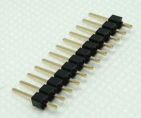
They have pins on both sides:

A-5776.jpg
Of course, so the boards will simply overlap. Here I was picturing all kinds of wiring haha.

Thanks!
 
Terrific builds on this thread!
For people who have already built an electrovibe: could you point me to the LDRs and Bulb you have used?
I just received my PCB today and I'm in the process of ordering the components, but hadn't any luck finding 9203 or 7532 LDRs anywhere.

Also, would Mouser 560-7371 bulb be correct?

Smallbear has the 9203 ldr and the 7371, that is what i used in both my electrovibe builds
 
Back
Top