Help with first time troubleshooting - Brown Betty

GazM

Member
Hi, hopefully someone can help me! Although this is my fourth pedal build, this is the first time it hasn't worked, so my first time trouble shooting pedal problems.

The issue: LED lights up, so doesn't seem to be a power issue. When the pedal is off, sound bypass's through the pedal no problem, therefore, I guess the mono jacks etc are all ok? However, when pedal is switched on, there is no sound.

I understand this might be a grounding issue? But i've checked all the solders and none of them seem to be touching. There is no sound when out of the enclosure either, so I don't think its the enclosure doing this.

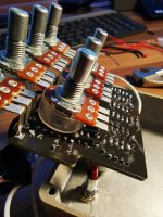
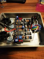
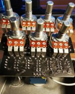
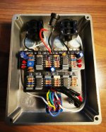
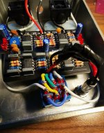
Can anyone see from my photos a rookie error that might be causing this? Or, what would be the next logical step in troubleshooting given my description?

Many thanks in advance!
 

Attachments

  • IMG_20230213_155754.jpg
    IMG_20230213_155754.jpg
    471.1 KB · Views: 26
  • IMG_20230213_161634.jpg
    IMG_20230213_161634.jpg
    539.3 KB · Views: 28
  • 1.JPG
    1.JPG
    152.8 KB · Views: 35
  • 2.JPG
    2.JPG
    120.9 KB · Views: 35
  • 3.JPG
    3.JPG
    123.2 KB · Views: 31
Solution
Welcome to the merry band of fools making exactly that kind of mistake every day.

Spent a hour troubleshooting a vero board build last week until I realized I had the signal in the OUT jack and the amp in the IN jack.

Which would be just silly and funny if it hadn't been at least the 3rd time I've done that in the last year...
I CANNOT F*CKING BELIEVE IT. Measured all IC pins this time correctly, pin 4's at zero this time, pin 8's at 8.83. thinking, ok so at least IC's are correct. read your last message. IVE PUT THE GOD DAMN SIGNAL IN THE OUT JACK. 3 pages of amazing support from all you guys, and its just user error. I'm so sorry to waste you guys time over this. how embarrassing. Thanks so much to all of you for helping...
Lets start with a few simple things while I go through the photos. Are the jacks wired correctly? I've not used that style of jack before, but sometimes when you wire them backwards, it will work in bypass but not when the effect is turned on, because you are sending the signal to ground. Also, have you adjusted the trimpot?...
 
Lets start with a few simple things while I go through the photos. Are the jacks wired correctly? I've not used that style of jack before, but sometimes when you wire them backwards, it will work in bypass but not when the effect is turned on, because you are sending the signal to ground. Also, have you adjusted the trimpot?...
Thanks for your help! The jacks I think are wired correctly, as I have used them in the other pedals and they worked this way around. The ground is going to the sleeve and the signal wire is going to the jack when its plugged in. Plus, I'm getting sound when in bypass so I am near certain the jacks are wired correctly.

The trim pot, I saw a video that said for a more BE-OD sound, turn it clockwise. So, I turned it all the way clockwise before ever trying it. As it didn't work, I tried with the trim pot all the way counter clockwise, still not working, and now I set the trim pot in the middle of the two extremes and still not working. Should I set the trim pot a specific way when first installing?

I have no idea, honestly. I'm just suggesting simple things that it might be, before I dive in to the schematic. Sometimes a trimpot will cut the signal in some settings. Looks like that shouldn't happen in the Brown Betty, so we can move on. You can try reflowing the solder joints. Some of them look like they might be suspicious, though that doesn't mean they are. We need to eliminate all the easy stuff before moving on to the complicated stuff...

From there you can start measuring voltages; like on the protection diode, and the Opamps. Work your way through the schematic measuring all the pins that are connected in someway to power (Vref/VDD). I'm not sure what they should be for each pin, but it will at least tell you if you are even getting power that far in the circuit...
 
Last edited:
I have no idea, honestly. I'm just suggesting simple things that it might be, before I dive in to the schematic. Sometimes a trimpot will cut the signal in some settings. Looks like that shouldn't happen in the Brown Betty, so we can move on. You can try reflowing the solder joints. Some of them look like they might be suspicious, though that doesn't mean they are. We need to eliminate all the easy stuff before moving on to the complicated stuff...

From there you can start measuring voltages; like on the protection diode, and the Opamps. Work your way through the schematic measuring all the pins that are connected in someway to power (Vref/VDD). I'm not sure what they should be for each pin, but it will at least tell you if you are even getting power that far in the circuit...
ok thanks, I will try to re-flow all joints, try again and come back to you!
 
ok thanks, I will try to re-flow all joints, try again and come back to you!
I have no idea, honestly. I'm just suggesting simple things that it might be, before I dive in to the schematic. Sometimes a trimpot will cut the signal in some settings. Looks like that shouldn't happen in the Brown Betty, so we can move on. You can try reflowing the solder joints. Some of them look like they might be suspicious, though that doesn't mean they are. We need to eliminate all the easy stuff before moving on to the complicated stuff...

From there you can start measuring voltages; like on the protection diode, and the Opamps. Work your way through the schematic measuring all the pins that are connected in someway to power (Vref/VDD). I'm not sure what they should be for each pin, but it will at least tell you if you are even getting power that far in the circuit...
Thanks mate, I'm now one step closer I think! re flowed all joints, and I now get sound when the pedal is switched on. However, all I get is loud humming with no guitar type sound. For example, the loud humming is there whether or not I play the guitar, and also turning any of the control pots seems to have no effect on the humming sound at all
.
 
That sounds like an issue with something grounding out.

The good news is that you are very, very close to this working. but finding the trouble spot can be annoyingly frustrating.

As Coda is directing, start with simple and obvious, then to the complex. I've built 30 or so pedals and only just a couple of days ago for the first time hand an issue with a bad chip.

Your assembly looks pretty tight but your solder joints are pretty globby. I'd say it's 90% likely that the issue is with a solder joint. I can't see the ones under the pots.
Audio Probe is definitely the best way to troubleshoot an issue like this.

Do you have one, or know how to make one?
it seems I have to go the audio probe route so will watch a few tutorials and see how I go! :) thanks for everyone's input so far, all very helpful!
 
If those work the same was as enclosed TRS jacks then I don't think they are wired correctly. I looks to me that all Tip and Ground wires are all attached to Tip connectors.
They should be wired correctly if hes getting bypass.

Maybe youre right though let me look at the schem for these.
 
Back
Top