PCB Guitar Mania - Fuzz Blaster

Does anyone have tips for PCB Guitar Mania boards? I've completed around 10 PedalPCB projects, a few from Moonn, some from GuitarPCB and have been able to get all of them working with a reasonable amount of troubleshooting (touch wood). But this is my first attempt at a PCBGM board and I'm stuck.

It's the Fuzz Blaster (their take on the DBA Supersonic Fuzz Gun) and seems fairly simple. Low parts count and easy to locate transistors. Layout isn't cramped and the instructions seem pretty ok. But I can't even get this thing to pass signal in bypass. My wiring looks correct based on their standard wiring guide. No shorts I can see, and everything is grounded as directed. Getting continuity on the jacks and the LED lights when the pedal is engaged. Perhaps I got a bad 3pdt? I used their "EZ 3pdt" daughterboard, but my next thought was to remove that and try to find a diagram on wiring directly to the switch lugs.

Hoping someone out there knows there is something i've missed that is required on PCBGM boards. I'm sure it's something simple that I'm just missing here.

(note: Yes, Q3 is in backwards... the instructions noted that if you want to use the same 2n5306 in that spot as DBA you have to flip the pinout by 180 degrees. Someone pointed that out on the PCBGM facebook page when I tried posting this in that spot. R3, R6 & R7 are also missing as there was an option to replace them with the trimmers.)

Thanks!
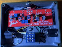
Fuzz Blaster.jpg
 
Solution
I usually use open jacks, but those enclosed jacks have the corner bevel lined up with the lug for ground right?

The jack on the left in the picture has two black wires soldered to a lug that doesn't look like it matches up with the bevel. Are those supposed to go to ground/ are you sure that one is right?
Tbh to my eyes the 3PDT soldering looks great!

...if you're planning on never removing it, that is 😅 Don't ask me how I know (I ended up pulling that daughterboard forcefully away and just throwing it in the bin, that did fix my issues though, and now if I solder in daughterboards I make sure they're well connected but I don't fill the holes just for that reason).

I think to be absolutely sure about the jacks you could...
True bypass (like you have here) only concerns the input and output jacks and the 3PDT. I can't tell from the picture (nor do I know those jacks) whether your input and output are wired correctly, but that would be my first guess. If they look correct, I would then try removing the EZ 3PDT and wire it straight - I think you can just use some PedalPCB build instructions and follow the wiring guide there. Desoldering the 3PDT is going to be a pain though, you should have a solder sucker for it IMO, not sure you can do it otherwise with that amount of solder.

To reiterate: 1.) quadruple check the jack wiring, maybe unscrew them and take better photos of which lugs they are wired to? And 2.) if they look correct, try going without the 3PDT daughterboard.

The issue is there since bypass isn't working, if the pedal still isn't working after you get bypass working, then you can move to more troubleshooting. But that's the first step IMO.
I've got the jacks wired up with ground going to the sleeve lug and the input (& output on the other side) on the tip lugs... according to the enclosed jack diagram on the PedalPCB Wiki (https://wiki.pedalpcb.com/wiki/Jacks). So I think that's correct and have checked the continuity with a multimeter, good there. Glad to hear my suspicions of the 3pdt being the culprit might be shared by someone else.

Removed a good amount of the solder with a solder sucker late last night, but not having a whole lot of luck getting the daughterboard off of there. I'm guessing I just used waaaay too much to attach in the first place. Will swap in a new one tonight. Thanks!
 
Tbh to my eyes the 3PDT soldering looks great!

...if you're planning on never removing it, that is 😅 Don't ask me how I know (I ended up pulling that daughterboard forcefully away and just throwing it in the bin, that did fix my issues though, and now if I solder in daughterboards I make sure they're well connected but I don't fill the holes just for that reason).

I think to be absolutely sure about the jacks you could check continuity from the other end of a cable to the jack while the other end of the cable is plugged in? Because the only things I can really think of is a.) the jacks are soldered wrong, b.) the daughterboard is broken, or c.) the 3PDT switch is broken, because at least the bypass should work if they're all correctly soldered. Oh, and just to be sure maybe make sure the cables you use are not broken, that can happen too of course.
 
I usually use open jacks, but those enclosed jacks have the corner bevel lined up with the lug for ground right?

The jack on the left in the picture has two black wires soldered to a lug that doesn't look like it matches up with the bevel. Are those supposed to go to ground/ are you sure that one is right?
Tbh to my eyes the 3PDT soldering looks great!

...if you're planning on never removing it, that is 😅 Don't ask me how I know (I ended up pulling that daughterboard forcefully away and just throwing it in the bin, that did fix my issues though, and now if I solder in daughterboards I make sure they're well connected but I don't fill the holes just for that reason).

I think to be absolutely sure about the jacks you could check continuity from the other end of a cable to the jack while the other end of the cable is plugged in? Because the only things I can really think of is a.) the jacks are soldered wrong, b.) the daughterboard is broken, or c.) the 3PDT switch is broken, because at least the bypass should work if they're all correctly soldered. Oh, and just to be sure maybe make sure the cables you use are not broken, that can happen too of course.
Looks like it was a bad 3pdt. Guess I'll start springing for the slightly more expensive ones. Thanks for your help!
 
Solution
Looks like it was a bad 3pdt. Guess I'll start springing for the slightly more expensive ones. Thanks for your help!
Glad you got it working! I can say I’ve successfully built two of them, so they’re good. Although, you’ve got to be careful with PCBMania boards. Not all of them work. I’ve had a couple duds. Also, funny all the boards I have built that sounded great, my 5 star reviews are up for everyone to see. Although, the couple that were duds, my reviews for those somehow didn’t make it up on the site….. Funny how that happens. Out of hundreds of pcbs built, it’s the only place that I’ve ever had non working pcbs. I can say the majority that I’ve built from them worked great. The Echo Nightmare, Green Lemon (this one is awesome), Acapulco Tone (another great pcb), Cherry Fuzz and Black Goat all worked wonderfully.
 
Back
Top