
thabigburrito
New member
Hi everyone,
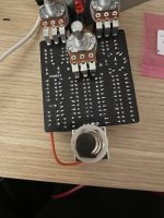
I’ve recently taken on a few builds, the most complicated being a phase II and (unsurprisingly) being the one with issues. Signal bypasses fine. When on, the indicator lights, the yellow LED turns on but does not vary in brightness, and the signal cuts. Playing very loud, I can get a fuzzy gating sound to come out, like a super misbiased fuzz pedal. There is also a significant amount of 15-17k oscillation hitting my interface (made troubleshooting that much more grating), but I'm not sure if that’s normal or not. Any advice would be much appreciated, thank you guys.
I’ve recently taken on a few builds, the most complicated being a phase II and (unsurprisingly) being the one with issues. Signal bypasses fine. When on, the indicator lights, the yellow LED turns on but does not vary in brightness, and the signal cuts. Playing very loud, I can get a fuzzy gating sound to come out, like a super misbiased fuzz pedal. There is also a significant amount of 15-17k oscillation hitting my interface (made troubleshooting that much more grating), but I'm not sure if that’s normal or not. Any advice would be much appreciated, thank you guys.
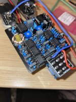
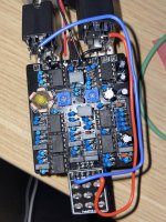


 . what's happening under the 470nf film caps? did a lead get bent and arcing to a resistor? doubt the power in wire is currently causing issues but that looks ready to break as well. take the IC's out, rub it down with some IPA on a cheap toothbrush(like you'd get to use on a dog) and see if it does the same thing once it's dry and chips back in.
