SOLVED Phase II No Work Right…

Coda

Well-known member
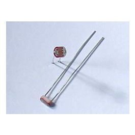
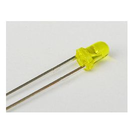
I get the filter, but no phase. The LED blinks, but it doesn’t seem to affect the tone. However…if I have it plugged in and on, and I move my finger towards the LED, or the TL072 just above, I can create the phase effect. It sounds great if I stand there and move my finger to and away from the top-left quadrant of the PCB…but I’m afraid that will take away from my showmanship, what having to stand there and manually create the effect…
 

Attachments

  • 2E8538F2-6229-4457-B0EB-0E9EF21A6576.jpeg
    2E8538F2-6229-4457-B0EB-0E9EF21A6576.jpeg
    120.8 KB · Views: 74
  • 46ED108B-2EB7-44E1-9080-8EFB1F57EA58.jpeg
    46ED108B-2EB7-44E1-9080-8EFB1F57EA58.jpeg
    112.1 KB · Views: 71
  • Like
Reactions: fig
it's all about dialing in a range of dim to less-dim range for the led, and the range of how-dim and how-light is set to whatever works best with the LDR.

set the rate to a slow speed and measure the voltage on the second leg of the depth pot when it is in the minimum and maximum rotations. let us know what you get on each one --- especially if it is a constant voltage that does not pulse or change speed when you make small adjustments to the rate pot.

With Depth at minimum I get a range between -.20 and .17, and by range I mean it jumps around a lot between those numbers. With Depth at maximum I get the same ranging jumping, only now it’s between -4.23 and 3.44…
 
With Depth at minimum I get a range between -.20 and .17, and by range I mean it jumps around a lot between those numbers. With Depth at maximum I get the same ranging jumping, only now it’s between -4.23 and 3.44i

does the LED dial down to turn off when you turn down the depth? if it is staying illuminated even at those low levels it may be getting some voltage through a different unintended path so you are limiting the range where it is working.
 
does the LED dial down to turn off when you turn down the depth? if it is staying illuminated even at those low levels it may be getting some voltage through a different unintended path so you are limiting the range where it is working.

I don’t remember 100%, but I think it goes off with the Depth at minimum. I’ll double-check in a little bit.
 
does the LED dial down to turn off when you turn down the depth? if it is staying illuminated even at those low levels it may be getting some voltage through a different unintended path so you are limiting the range where it is working.

Update: with Depth at minimum the LED does NOT go completely out. It does go out when Depth is up, and Rate is up as well…you know…it pulses from off to on. It goes completely out then.
 
Last edited:
How bright/dark the LED goes is going to depend on the trim pot settings. TR1 should adjust the DC bias (idle brightness) when the LFO is stationary.

This is baffling... If the LED is pulsing the LFO is working.

If sweeping your hand in front of the LDRs sweeps the phase then the all-pass filters / signal path are both working.
 
I'm sure I could have arranged them neater, but I doubt that would cause the problem.
This is a pretty forgiving circuit when it comes to the ldr placement. I actually fit them flat to the pcb like flower pedals. And I never touch the trimmers on these. Center noon is perfect.
 
I think tomorrow I’ll pull out my audio probe, and check the mix at IC5. If I can hear the phasing at the IC, I’ll know the issue is after that. If I don’t hear any phasing I’ll know it’s something before it. You know…science.
 
A thought: I can already hear the phasing using the manual technique, so that means IC5 is working. No need to go probing. Back to the drawing board…
 
  • Like
Reactions: fig
No very scientific but try pressing each phase stage IC or placing your finger on the solder joints of the bits it starts phasing at

I can't remember where I read it but I recall reading somewhere that if you've got a dodgy phase stage ie if it puts the signal exactly on top of the preceding signal you'll get clean slightly amplified signal ie in phase not 180° out or whatever it should be with 6 stages

I actually think it was a mutron phasor 2 but not 100%

But the guy didn't have a magic finger like yours so it doesn't explain that

I would say that it totally seems plausible. But given the fact that I can manually create phase, it seems like the IC’s are ok. Though, thinking about it. Maybe the IC’s aren’t amplifying the phased signal enough, and it’s too low in the mix?…
 
Back
Top