Haarp no sound

y2kornfreak

New member
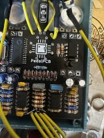
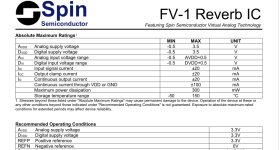
I just built a Haarp pedal. everything lights up, bypass mode has sound running through it but when I turn it on, it goes completely quiet. Saw another post saying it could be the FV-1 chip, so i tried going through each leg with the solder and the problem is still there
 

Attachments

  • IMG_4101.jpeg
    IMG_4101.jpeg
    397.3 KB · Views: 30
  • IMG_4100.jpeg
    IMG_4100.jpeg
    496.8 KB · Views: 31
  • Like
Reactions: fig
If the Dry control doesn't give you a clean signal the problem is not the FV-1 IC.

That's not to say there couldn't be an additional problem there as well, but I'd focus on the dry signal first.
 
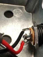
Let's see your stomp switch wiring
This one. If you have bypass but no effected signal, all the offboard wiring would be the first place I would look. Sometimes I wire to the wrong terminal (S instead of T) or I make a poor quality joint and the wire slips.

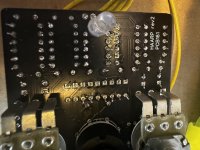
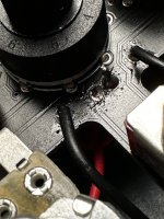
I can't really tell if it's a real thing or just the photo, but some of the solder joints, esp. around the row of diodes look low (?) In any case, reflowing all your joints and making sure they are pretty Mt. Fuji volcano shapes is standard operating procedure for troubleshooting.
 
so i got brand new wires and redid everything. i realized trying a method where i made a little loop around the holes with the wire before soldering made it weak and it broke... so everything was ok and it was playing right and turned on! but now theres a new problem...

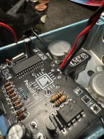
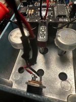
when i tested it at first, it was outside of the enclosure, but when i put everything inside and tested again, it won't turn on. i suspected it was the AC plug because it was touching the toggle switch near the top, so i took it out but still nothing. i then thought it was the ac plug itself because i accidentally burned the plastic (it was the small low profile jack), so i replaced the plug it with a regular size innie jack. it seemed to work again like normal, so i put it back in the case... and realized it was still touching the toggle switch and stopped working. i then took it out and got a rubber heat shrink tube to cover the one spare pole that would touch and still no power, even while outside the enclosure... am i missing something? or is it bad wire? the wire is still working in my data corrupter so im not sure what i'm doing wrong, or maybe i twisted and turned it so much that it got bad?
do you have pot covers on the backs of the pots?
 
I don't see anything obvious, but there's a lot of exposed leads and wires in there. Have you tried putting some pressure on the switches ? Tried different positions on the rotary ?
 
If the pos lug of the DC jack touched the top lug of the Spdt switch you just juiced the 3v side of the circuit with 9v…. 😬… the good news, even when it does work it’s hard to find a practical use for this effect.
 
Last edited:
If the pos lug of the DC jack touched the top lug of the Spdt switch you just juiced the 3v side of the circuit with 9v…. 😬… the good news, even when it does work it’s hard to find a practical use for this effect
does that mean i have to install a new FV-1? i was afraid of that happening, but even with the lumberg DC, the wires was covered in heat shrink tubing both times. i just forgot to cover the 3rd pole for the innie dc jack... so yeah, still making noob moves on my 5th pedal
 
also, wouldnt the pedal itself still turn on even if the FV-1 was fried? i imagine i'd just get a crazy noise if it was damaged, but the pedal doesnt light up at all like before
 
Last edited:
The only way a defective FV-1 would cause no sound and no LED is if it was dead shorted, pulling the 3.3V and in turn the 9V supply down with it.

Things would be getting hot if this was the case. Is the FV-1 IC or 3.3V regulator hot?

Do you have a DMM? If so, check the voltages on the two outer pins of the L78L33 regulator. You should have 9V and 3.3V.
 
I’m not sure if I completely understand the situation but I would initially do want Robert suspended and check the regulator and the rest of the power section, if you are getting appropriate voltages at all necessary pins and no shorts to ground, I would audio probe it. there isn’t a ton of components. So if you have never done it before this might not be a bad one to start with
 
Back
Top