I've been using two breakout boards in all of my recent builds.
One is an I/O board with MOSFET-based over-voltage and reverse polarity protection; the other is a "smart" microcontroller-based relay bypass board.
I'm playing around with combining them into a single board that uses some of the (relatively) new ATTINY 1-series microcontrollers:

The 1-series has a lot of advantages over the earlier ATTINY microcontrollers, including UPDI programming, which allows you to program the microcontroller with just three terminals. The three terminals are hidden under the output jack, so they won't obtrude in an assembled build. (The jacks would hide the unsightly vias, too.) And they're cheap, too, around 55¢ from Digikey or Mouser.
Here's the schematic, for anyone who's curious:

One other feature that I've been working on is an over-voltage warning indicator. My previous iterations of the microcontroller included an unused pin, PA7. The new version connects that pin (PA7) to the junction of a 7.5v zener diode and a 1M resistor:
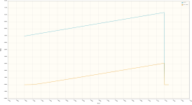
As the VCC increases above the zener voltage (V
Z), the voltage at PA7 increases by VCC-V
Z, until the over-voltage circuit kicks in, at which point the voltage at PA7 decreases to a few nanovolts:
When the microcontroller detects that the voltage at PA7 is below a certain level, say 0.5v, it would start to blink the bypass LED, warning the user of over-voltage. Without the blinking LED, there's a sizeable chance that the user would just think that the pedal was broken.
This might seem like over-engineering to some, but I've seen over-voltage kill many more pedals recently than reverse polarity. As a bonus, it's not meaningfully more expensive than just doing a relay bypass breakout board.